


Appendix 1 - 5
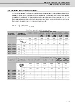
MDS-D-SVJ3/SPJ3 Series Specifications Manual
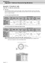
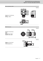
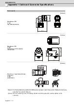
Appendix 1-2 Cable connection diagram
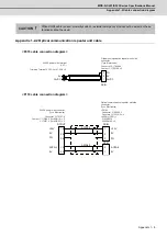
Appendix 1-2-2 Optical communication repeater unit cable
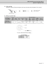
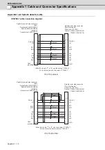
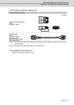
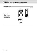
< F070 cable connection diagram >
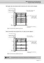
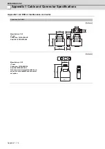
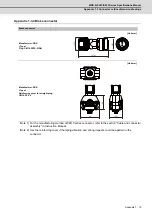
< F110 cable connection diagram >
When DG24 cable is used, proximity switch or external emergency stop cannot be wired, so these
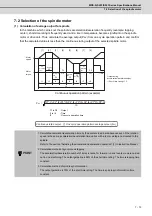
functions cannot be used.
CAUTION
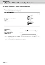
DCIN
0V
FG
1
2
3
0V
Optical communication repeater unit side
connector
(Tyco Electronics)
24VDC power side terminal
(J.S.T.)
Crimping Terminal
:
V1.25-3 or V1.25-4 × 2
24VDC
24VDC
Connector
:
2-178288-3
Contact
:
1-175218-5 × 3
+24V
0V
FG
ACFAIL
0V
1B
2B
3B
1A
2A
1
2
3
2
1
+24V
0V
FG
ACFAIL
0V
AWG16
AWG22
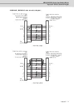
DCOUT
DCIN
CF01
<ACFAIL (CF01)>
51030-0230
50084-8160 × 2
24VDC power side connector
(Tyco Electronics)
Connector
:
3-178127-6
Contact
:
1-175218-5 (for AWG16 ) × 3
1-175217-5 (for AWG22 ) × 2
Optical communication repeater unit side
connector
(Tyco Electronics)
<DCIN>
Connector
:
2-178288-3
Conntact
:
1-175218-5 × 3
Summary of Contents for MDS-D-SPJ3
Page 1: ......
Page 3: ......
Page 5: ......
Page 17: ......
Page 19: ......
Page 21: ......
Page 27: ......
Page 31: ......
Page 39: ...1 8 ...
Page 65: ...2 26 ...
Page 93: ...3 28 ...
Page 169: ...5 58 ...
Page 233: ...Appendix 2 10 ...
Page 257: ...Appendix 4 20 ...
Page 280: ......
Page 284: ......


