5 - 7
MDS-D-SVJ3/SPJ3 Series Specifications Manual
5-1 Servo options
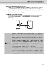
(d) Wiring of the battery voltage drop warning output
The battery voltage drop warning is detected in the MDS-BTBOX-36 and output to the servo drive unit
as digital signal.Connect the battery voltage drop warning signal to one of the servo drive units
supported by MDS-BTBOX-36. For the connected servo axis, set the servo parameter "SV082/bitF-C"
to "2" to enable this signal input. When using 2 or 3-axis drive unit, set the value to one of the axes and
set other axes in the same unit to "0" (No signal).
(e) When backing up for more than 8 axes
Add a MDS-BTBOX-36 so that the number of connectable axes for a battery unit is 8 axes or less.
For all of servo drive units supported by one MDS-BTBOX-36, start the control powers ON
simultaneously.
1. The battery voltage drop warning signal and safety observation function door state signal cannot
be connected to the same drive unit. To use these function together as a system, connect to the
different drive unit.
2. Battery voltage drop warning (9F) can also occur when the cable between the battery box and
drive unit is broken.
3. For 2-axis or 3-axis drive unit, the parameter error "E4" or drivers communication error "82" occurs
at all the axes when the setting of SV082(SSF5)/bitF-C differs according to axes (except 0 setting).
4. The drive unit which is connected to the battery box and cell battery cannot be used together.
5. Replace the batteries with new ones without turning the control power of the drive unit OFF
immediately after the battery voltage drop alarm (9F) has been detected.
6. Replace the batteries while applying the control power of all drive units which are connected to the
battery box.
7. When changing the wiring of the CN9 control input, change after SV082(SSF5)/bitF-C is set to 0.
Otherwise unexpected alarms can be detected because of a mismatch of the control input signal
and setting parameter.
MDS-BTBOX-36
DOCOM
DO(ALM)
24V
+5V
LG
CN9
4
1
20
13
Servo drive unit
Battery voltage drop warning signal connection diagram
CAUTION
Summary of Contents for MDS-D-SPJ3
Page 1: ......
Page 3: ......
Page 5: ......
Page 17: ......
Page 19: ......
Page 21: ......
Page 27: ......
Page 31: ......
Page 39: ...1 8 ...
Page 65: ...2 26 ...
Page 93: ...3 28 ...
Page 169: ...5 58 ...
Page 233: ...Appendix 2 10 ...
Page 257: ...Appendix 4 20 ...
Page 280: ......
Page 284: ......

