


5 - 43
MDS-D-SVJ3/SPJ3 Series Specifications Manual
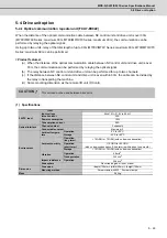
5-4 Drive unit option
< R-UNIT-5 >
[Unit: mm]
Type
Regenerative
capacity (W)
Resistance
value (
)
Mass (kg)
R-UNIT-5
3100
10
15.0
2. Attach packing to the flange section.
3. Do not wire or arrange other devices in front of the section marked with a
as extremely hot wind
will be blown out.
4. For the installation direction of this resistor, the "Ceiling" is the top and "Ground" is the bottom.
5. Touching the resistor when it is hot could lead to burns. Always install a protective cover or
consider the installation site so that workers will not touch the unit.
6. The resistor's heating value will differ according to the acceleration/deceleration frequency, speed
being used and the load GD
2
conditions, etc. However, install the resistor so that the hot wind is
always exhausted to outside the panel.
7.5
360
7.5
375
1.6
18
120
120
18
276
23 20
140
23
255
75
75
98
340
22
160
6
91
29
3-Φ6
TE1
4
4
#.
#.
#%
#%
E
259
6-M5 x 0.8
345
360
120 120
R1
R2
AL
1
AL
2
AC1
AC2
E
Punch
hole
Suction
screw
Embedded installation
(Installation hole dimensions)
-4
l:
Terminal screw size:
M4 x 0.7 screw
Applicable crimp termina
Bare round terminal up to 5.5
Terminal layout
(Earth terminal)
Hot wind discharge
Ceiling
Ground
Embedded installation
(outer heat radiating section)
hole
Power for fan
AC200V, 50/60Hz
32/30W, 0.21/0.19A
CAUTION
★
Summary of Contents for MDS-D-SPJ3
Page 1: ......
Page 3: ......
Page 5: ......
Page 17: ......
Page 19: ......
Page 21: ......
Page 27: ......
Page 31: ......
Page 39: ...1 8 ...
Page 65: ...2 26 ...
Page 93: ...3 28 ...
Page 169: ...5 58 ...
Page 233: ...Appendix 2 10 ...
Page 257: ...Appendix 4 20 ...
Page 280: ......
Page 284: ......


