NOTE
To confirm the above operation, check the local header!!
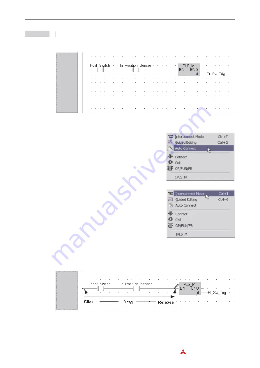
The display should be as follows:
Finally, the ladder network must be finalised by connecting up the elements as follows.
Note that the Pointer now changes to a small pencil icon.
햹
On the Ladder diagram click on the left point on the ladder diagram and “Click – Drag”
across the diagram and release on the ‘EN’ input on the ‘PLS_M’ function as shown below:
The circuit is now complete.
Application Program
Building a Project
4 - 20
MITSUBISHI ELECTRIC
햷
Right click the mouse anywhere in the edit window
area and de-select the
Auto connect
function.
햸
In the same manner, click to select
Interconnect
Mode
.
Summary of Contents for FX2N-32CAN
Page 1: ...MITSUBISHI ELECTRIC FACTORY AUTOMATION Programmable Logic Controllers GX IEC Developer ...
Page 2: ......
Page 4: ......
Page 6: ......
Page 10: ...IV MITSUBISHI ELECTRIC ...
Page 18: ...Modular PLC Training Hardware Course Overview and Requirements 1 2 MITSUBISHI ELECTRIC ...
Page 176: ...Device Edit 8 4 MITSUBISHI ELECTRIC ...
Page 190: ...Assigning DUT Variables to Function Blocks Data Unit Types DUT 10 10 MITSUBISHI ELECTRIC ...
Page 198: ...Array Example Single Dimension Array Arrays 11 8 MITSUBISHI ELECTRIC ...
Page 219: ...Sequential Function Chart SFC SFC Elements Training Manual GX IEC Developer 14 3 ...
Page 230: ...Structured Text Program Example IEC Structured Text 16 4 MITSUBISHI ELECTRIC ...
Page 278: ...PLC Components Glossary Appendix A 18 MITSUBISHI ELECTRIC ...
Page 283: ......


