background image

INVERTER SETTING

20

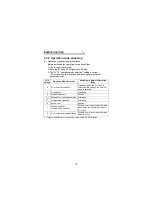
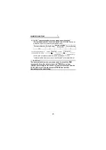
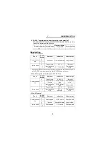
2) Pr. 501  "communication error occurrence count display"

The cumulative number of communication error occurrences can be
indicated. Write 0 to erase this cumulative count.

At the point of communication line fault occurrence, Pr. 501 
"communication error occurrence count display" is incremented by 1.

Parameter Number Setting Range

Minimum Setting 

Increments

Factory Setting

501 0

1

0

CAUTION

The communication error occurrence count is stored into RAM 
temporarily. Since this data is stored in E

2

PROM at one-hour 

intervals, performing power-on reset or inverter reset may cause the 
Pr. 501 data to be the value stored in E

2

PROM the last time 

depending on the reset timing.

Normal

Abnormal

Count timing depending on
communication line status

Incremented by 1

Normal

Abnormal

Incremented by 1

Summary of Contents for FR-A5NPA

Page 1: ...FR A5NPA Frequency Inverter Instruction Manual Profibus DP Communication Option INDUSTRIAL AUTOMATION MITSUBISHI ELECTRIC MITSUBISHI ELECTRIC Art no 146529 01 02 2003 Version B IB NA 0600095 B ...

Page 2: ...ious consequence according to conditions Please follow the instructions of both levels because they are important to personnel safety SAFETY INSTRUCTIONS While power is on or when the inverter is running do not open the front cover You may get an electric shock Do not run the inverter with the front cover removed Otherwise you may access the exposed high voltage terminals and charging part and get...

Page 3: ...s correct Prevent screws metal fragments or other conductive bodies or oil or other flammable substance from entering the inverter Before starting operation confirm and adjust the parameters A failure to do so may cause some machines to make unexpected motions Do not modify the equipment When parameter clear or all parameter clear is performed each parameter returns to the factory setting Re set t...

Page 4: ... 2 1 Operation mode indication 9 3 2 2 Operation mode switching 10 3 3 Operation and Speed Command Source 15 3 3 1 FR A500 F500 series 15 3 3 2 FR V500 series 17 3 4 Operation at Communication Error Occurrence 19 3 4 1 Operation selection at communication error occurrence For the FR A500 V500 series only 19 3 4 2 Alarm and measures 23 3 4 3 Inverter reset 24 3 5 Instructions 24 4 FUNCTION OVERVIEW...

Page 5: ... 50 7 2 5 Terminal input read 50 7 2 6 Inverter reset 50 7 2 7 Node address read 51 7 2 8 Alarm history 51 7 2 9 PNU list read 52 7 3 Standard Parameters 53 8 PARAMETER DEFINITIONS V500 SERIES 56 8 1 Outline of PNU 56 8 2 Profibus PNU 57 8 2 1 Real time monitor 57 8 2 2 Parameter clear 59 8 2 3 Operation mode read write 59 8 2 4 Set frequency read 59 8 2 5 Terminal input read 60 8 2 6 Inverter res...

Page 6: ... manufactured in and after May 2002 Any of the models may be used with this unit if its SERIAL number indicated on the rating plate and package has 25 or later version For details on the SERIAL number please contact your sales representative SERIAL is made up of 1 version symbol 1 alphabet letter or numeric character indicating month and 7 numeric characters indicating year and control number as s...

Page 7: ...ps on During communication Profibus connector Dsub9 pin connector Used to connect a Profibus cable for Profibus communication Refer to page 7 FR A5NPA Front view Option fixing hole Mounting hole Rear view connector Node address switch Operating status indicator LED Mounting hole Profibus connector Dsub9 pin connector 01 2 3 4 5 6 7 8 9 A B C D E F 01 2 3 4 5 6 7 8 9 A B C D E F SW2 SW1 Mounting ho...

Page 8: ... to be connected with a connector can be mounted dismounted to from the inverter front face Number of node occupied One inverter occupies one node Cable For 12Mbps communication compliant with EEIA RS 485 standard Communication speed Wiring length 1200m maximum 9600bps 19 2Kbps 93 75Kbps Wiring length 600m maximum 187 5Kbps Wiring length 200m maximum 500Kbps 1 5Mbps Wiring length 100m maximum 3Mbp...

Page 9: ...ing on the inverter is not made valid The node address setting is made valid either after power is reapplied or when the RES signal turns on 4 You cannot set the same node address to other devices on the network Such setting disables normal communication Set the arrow of the corresponding switch to the required numeral Example For node address 1H Set of SW1 to 0 and of SW2 to 1 For node address 7D...

Page 10: ...s it is available in Aug 2000 3 Securely fix the option unit to the inverter on both sides with the accessory mounting screws If the screw holes do not line up the connector may not have been plugged snugly Check for loose plugging 4 Reinstall the front cover of the inverter Refer to the inverter manual 5 Connect a Profibus communication cable to the Profibus connector Dsub9 pin connector of the o...

Page 11: ...ixed by the hook of the inverter REMARKS Perform wiring after the option unit FR A5NPA was fitted and the inverter front cover was mounted The option unit FR A5NPA is valid only if it is fitted in slot 3 When two or more communication option units are mounted E OPT error is displayed Note that when the relay output computer link unit FR A5NR is mounted only relay output is activated ...

Page 12: ...ting resistor If the nodes at both ends of the network are the FR A5NPA and inverter connect a connector with a built in terminating resistor Dsub9 pin type male connector pin number Signal Application 1 SHIELD Shield 2 N C Unconnected 3 RxD TxD Receive transmit data 4 RTS 1 Control signal transmission request from the inverter 5 DGND 2 Data earth 6 5VDC 2 Voltage output 7 N C Unconnected 8 RxD Tx...

Page 13: ...o 2 1 0 12 500 1 Communication error recognition waiting time 0 to 999 8s 0 1s 0 19 501 1 Communication error occurrence count display 0 1 0 20 502 1 Communication error time stop mode selection 0 to 2 1 0 21 Parameter Number Name Setting Range Minimum Setting Increments Factory Setting Refer to page 338 Operation control command source 0 1 1 0 17 339 Speed command source 0 1 1 0 17 340 Link start...

Page 14: ...ter 3 Network operation NET Controls the inverter with instructions from the Profibus master module via the option unit FR A5NPA The operation signal and running frequency can be entered from the control circuit terminals depending on the Pr 338 operation control command source and Pr 339 speed command source setting 3 2 1 Operation mode indication FR DU04 1 FR PU04 V Hz A V MON EXT PU CONTROL PAN...

Page 15: ...with the FR A500 series Pr 79 Setting Operation Mode Selection Switching to Network Operation Mode 0 PU or external operation Disallowed when the PU mode is selected Allowed when the external mode is selected 1 PU operation Disallowed 2 External operation Allowed 3 4 External PU combined operation Disallowed 5 1 Programmed operation Disallowed 6 Switch over Allowed 7 External operation PU operatio...

Page 16: ...mode via Profibus master module E PU operation Network operation Switching disallowed Allowed if external operation is selected in A and network operation is then selected in C 1 F Network operation PU operation Switching disallowed Allowed if external operation is selected in D and PU operation is then selected in B 1 CAUTION 1 When 1 or 2 is set in Pr 340 link startup mode selection the operatio...

Page 17: ...mode Input running frequency running speed from the PU and the start signal from outside 4 External PU combined operation Inverter operates in the external PU combined operation mode Input running frequency running speed from outside and the start signal from the PU 5 1 Programmed operation Inverter operates in the programmed operation mode 6 Switch over Inverter operates in the external operation...

Page 18: ...he external PU combined operation mode Input running frequency running speed from outside and the start signal from the PU 5 1 Programmed operation Inverter operates in the programmed operation mode 6 Switch over Inverter operates in the network operation mode Operation mode is switched while running Refer to the inverter manual for details 7 PU operation interlock X12 signal ON Inverter operates ...

Page 19: ...like during network operation remains stopped even if power is recovered 3 When Pr 340 2 When a start command is given from the network with restart enabled Pr 57 9999 a start command during power off including instantaneous power failure and power failure is stored Therefore the inverter resumes operation in the state before powering off at powering on again power restoration ...

Page 20: ...ings 0 Low speed operation command RL NET External NET External Pr 59 0 1 Middle speed operation command RM NET External NET External Pr 59 0 2 High speed operation command RH NET External NET External Pr 59 0 3 Second function selection RT NET NET External External 4 Current input selection AU Combined Combined 5 Jog operation selection JOG External External 6 Automatic restart after instantaneou...

Page 21: ...s mounted The FR A5AP cannot be used with the FR F500 series 4 Programmed operation is available only with the FR A500 series Selective functions Pr 180 to Pr 186 settings 17 Load pattern selection forward reverse rotation boost switching X17 NET NET External External 18 Magnetic flux V F switching X18 NET NET External External 19 Load torque high speed frequency X19 NET NET External External 20 S...

Page 22: ...ng 1 Middle speed operation command Remote setting deceleration RM NET External NET External 2 High speed operation command Remote setting acceleration RH NET External NET External 3 Second function selection RT NET NET External External 5 Jog operation selection JOG External External 8 15 speed selection REX NET External NET External 9 Third function X9 NET NET External External 10 FR HC connecti...

Page 23: ...e MRS signal is assigned for both network and external control the output stop command is as indicated in the following table Network External Output Stop Command Pr 17 0 Pr 17 2 ON ON Output stopped Output not stopped ON OFF Output stopped Output stopped OFF ON Output stopped Output stopped OFF OFF Output not stopped Output stopped ...

Page 24: ... communication error If the communication line fault still persists after the time set in Pr 500 has elapsed it is recognized as a communication error When the fault is restored to normal communication within the set time it is not regarded as a communication error and operation continues REMARKS For the FR A500 Pr 500 to Pr 502 are available with an upgraded inverter Refer to the inverter manual ...

Page 25: ...emented by 1 Parameter Number Setting Range Minimum Setting Increments Factory Setting 501 0 1 0 CAUTION The communication error occurrence count is stored into RAM temporarily Since this data is stored in E2 PROM at one hour intervals performing power on reset or inverter reset may cause the Pr 501 data to be the value stored in E2PROM the last time depending on the reset timing Normal Abnormal C...

Page 26: ...tion Alarm output Communication line 0 Continued Normal indication Not provided 1 2 Option itself 0 Coast to stop E 3 lit Provided 1 2 Decelerated to stop E 3 lit after stop Provided after stop Fault Pr 502 Setting Operation Indication Alarm output Communication line 0 Coast to stop E OP3 lit Provided 1 Decelerated to stop E OP3 lit after stop Provided after stop 2 Decelerated to stop E OP3 lit af...

Page 27: ... a restart is the one given before the fault occurrence 6 When the setting was made to provide an alarm output the fault definition is stored into the alarm history The fault definition is written to the alarm history when an alarm output is provided When no alarm output is provided the fault definition overwrites the alarm indication of the alarm history temporarily but is not stored After the fa...

Page 28: ...ion Stop Stop Stop Option itself Communi cation option con nection fault Inverter operation Inverter trip Depends on the Pr 502 setting Inverter trip Depends on the Pr 502 setting Inverter trip Depends on the Pr 502 setting Data commu nication Continued Continued Continued FR A5NPA alarm Inverter operation Continued Continued Inverter trip Depends on the Pr 502 setting Data commu nication Stop Sto...

Page 29: ...owed Disallowed Error reset at inverter fault Reset can be made only when the protective function of the inverter is activated Allowed Allowed Allowed Connect terminals RES SD Allowed Allowed Allowed Switch off inverter power Allowed Allowed Allowed CAUTION 1 When a communication line fault has occurred reset cannot be made from the Profibus master module 2 The inverter is set to the external oper...

Page 30: ...xternal operation Network operation Profibus Operation command Output frequency setting Disallowed Disallowed Allowed Monitor Allowed Allowed Allowed Parameter write Disallowed 3 Disallowed 3 Allowed 3 Parameter read Allowed Allowed Allowed Inverter reset Disallowed Disallowed Allowed 1 Error reset at inverter fault Allowed 1 Allowed 1 Allowed 1 Stop command 2 Disallowed Disallowed Allowed Control...

Page 31: ... 45 3 Parameter write You can write a function from the master module Note that writing a function during inverter operation will result in a write mode error Refer to pages 35 42 Refer to the inverter manual for parameter details 4 Inverter reset You can reset the inverter or reset an inverter error Refer to pages 37 44 50 60 FR A500 F500 series FR V500 series Terminal Operation Command Signal Te...

Page 32: ...eries and page 57 for the FR V500 series 4 Inverter status Inverter output signal can be monitored by the PNU Refer to pages 38 45 2 Parameter read You can read a function to the master module Refer to pages 35 42 Refer to the inverter manual for parameter details FR A500 F500 series FR V500 series Output Definition Signal Output Definition Signal Inverter running RUN Inverter running RUN Forward ...

Page 33: ...upp 0 FMS Field Bus Message Specifications not supported Hardware_Release Series A Hardware version Software Release Revision 2 00 Software version 9 6_supp 1 Communication speed 9600bps support 19 2_supp 1 Communication speed 19 2Kbps support 93 75_supp 1 Communication speed 93 75Kbps support 187 5_supp 1 Communication speed 187 5Kbps support 500_supp 1 Communication speed 500Kbps support 1 5M_su...

Page 34: ... between 2 polling cycles Modular_Station 1 Modular device specified Max_Module 1 Maximum number of modules 1 Max_Input_Len 28 Input data Maximum 28 bytes Max_output_Len 28 Output data Maximum 28 bytes Max_Data_Len 56 Input and output data Maximum 28 28 56 bytes Fail_Safe 0 Failsafe not supported Max_Diag_Data_Len 6 Diagnostic data of 6 bytes secured no external diagnosis Slave_Family 1 Drives def...

Page 35: ...r parameter s second byte Ext_User_Prm_Data_ Ref 1 1 Byte swapping selection 1 is used on text base in user parameter s second byte Module PPO type 1 F3H F1H PPO type 1 selection EndModule Module PPO type 2 F3H F5H PPO type 2 selection EndModule Module PPO type 3 F1H PPO type 3 selection EndModule Module PPO type 4 F5H PPO type 4 selection EndModule Module PPO type 5 F3H F9H PPO type 5 selection E...

Page 36: ...are not used Low bits Bits 0 to 15 Parameter value PZD STW ZSW STW Control word command request ZSW Status word command response HSW HIW HSW Set frequency set speed command request HIW Running frequency running speed command response ECW ESW ECW Extended control word command request ESW Extended status word command response Reserved Reserved area for extension 1 word PKE IND PWE STW ZSW HSW HIW PP...

Page 37: ...de with switchover function does not allow the network operation mode enabled command to be executed due to the same contents as that sent last time Therefore the operation mode remains the PU operation mode without changing to the network operation mode In this case send another command as PU operation mode enabled from the master once then send the network operation mode enabled command again PK...

Page 38: ... bit reserved 31 30 29 28 27 26 25 24 23 22 21 20 19 18 17 16 bit PWE set value 151413121110 9 8 7 6 5 4 3 2 1 0 bit 0 0 0 0 0 0 0 0 0 0 0 0 0 0 0 0 PWE STW RAM E2PROM 151413121110 9 8 7 6 5 4 3 2 1 0 bit 0 0 1 1 1 1 1 1 MRS RT STR STF PZD enable Not support Fault reset Not support Operation enable Not support HSW set frequency HSW 151413121110 9 8 7 6 5 4 3 2 1 0 bit ECW RH 151413121110 9 8 7 6 5...

Page 39: ...t PWE read value 151413121110 9 8 7 6 5 4 3 2 1 0 bit 0 0 0 0 0 0 0 0 0 0 0 0 0 0 0 0 PWE ZSW Busy 151413121110 9 8 7 6 5 4 3 2 1 0 bit 1 0 0 1 1 1 1 1 NET mode REW FWD RUN FU Power on inhibit Not support Fault Not support HIW operation frequency HIW 151413121110 9 8 7 6 5 4 3 2 1 0 bit ESW SU 151413121110 9 8 7 6 5 4 3 2 1 0 bit 0 0 0 0 0 OL Alarm Not support Control request Slave Master command ...

Page 40: ...rameter value array is requested read request 7 Parameter value array word is changed write request 8 to 15 Not supported Command response 0 No response 1 Parameter value word is transferred 2 to 3 Not supported 4 Parameter value array word is transferred 5 to 6 Not supported 7 Command execution error error number is stored into PWE 8 to 15 Not supported IND 0 to 7 Reserved area for extension 0 is...

Page 41: ...nvalid PNU 1 Parameter value unchangeable This error also occurs when Pr 77 1 2 Outside setting range 3 Invalid Sub Index number 4 No array 11 No parameter change right 18 Other error 1 Outside AK number range Write data error External operation error Without option error Instruction code error With STF error With STR error With operation mode specification error Calibration error Pr 900 and later...

Page 42: ... 11 0 OFF 1 ON Forward rotation command STR signal 12 0 OFF 1 ON Reverse rotation command RT terminal 13 0 RT OFF 1 RT ON Factory set to the second function selection Pr 183 can be used to change the signal 2 MRS signal 14 0 OFF 1 ON Output shutoff RAM E2 PROM 15 0 Set frequency HSW is written to RAM Power on reset returns the changed set frequency to the setting before it was written to RAM 1 Set...

Page 43: ...tation operation being performed REW 13 0 Other than reverse operation being performed at a stop forward rotation operation being performed 1 Reverse rotation operation being performed Operation mode 14 0 Other than network operation mode 1 Network operation mode BUSY 15 0 Ready status 1 Busy status If it takes time to perform slave side processing slave side busy status is announced since reply t...

Page 44: ... set to current input selection Pr 184 can be used to change the signal 1 CS terminal 5 0 CS OFF 1 CS ON Factory set to automatic restart after instantaneous power failure selection Pr 186 can be used to change the signal 1 6 7 Not used 0 is set Command count 8 to 15 Used by the master to recognize the command response ESW SU signal 0 0 OFF 1 ON Up to frequency OL signal 1 0 OFF 1 ON Overload alar...

Page 45: ...served 31 30 29 28 27 26 25 24 23 22 21 20 19 18 17 16 bit PWE set value 151413121110 9 8 7 6 5 4 3 2 1 0 bit 0 0 0 0 0 0 0 0 0 0 0 0 0 0 0 0 PWE STW RAM E2PROM 151413121110 9 8 7 6 5 4 3 2 1 0 bit 0 0 1 1 1 1 1 1 MRS DI11 STR STF PZD enable Not support Fault reset Not support Operation enable Not support HSW set speed HSW 151413121110 9 8 7 6 5 4 3 2 1 0 bit ECW DI1 151413121110 9 8 7 6 5 4 3 2 1...

Page 46: ...bit PWE read value 151413121110 9 8 7 6 5 4 3 2 1 0 bit 0 0 0 0 0 0 0 0 0 0 0 0 0 0 0 0 PWE ZSW Busy 151413121110 9 8 7 6 5 4 3 2 1 0 bit 1 0 0 1 1 1 1 1 NET mode REW FWD RUN FB Power on inhibit Not support Fault Not support HIW operation speed HIW 151413121110 9 8 7 6 5 4 3 2 1 0 bit ESW SU 151413121110 9 8 7 6 5 4 3 2 1 0 bit 0 0 0 0 0 OL Alarm Not support Control request Slave Master command re...

Page 47: ...eter value array is requested read request 7 Parameter value array word is changed write request 8 to 15 Not supported Command response 0 No response 1 Parameter value word is transferred 2 to 3 Not supported 4 Parameter value array word is transferred 5 to 6 Not supported 7 Command execution error error number is stored into PWE 8 to 15 Not supported IND 0 to 7 Reserved area for extension 0 is se...

Page 48: ...lid PNU 1 Parameter value unchangeable This error also occurs when Pr 77 1 2 Outside setting range 3 Invalid Sub Index number 4 No array 11 No parameter change right 18 Other error 1 Outside AK number range Write data error External operation error Without option error Instruction code error With STF error With STR error With operation mode specification error Calibration error Pr 900 and later Re...

Page 49: ...al 12 0 STR OFF 1 STR ON Factory set to reverse rotation command Pr 187 can be used to change the signal 2 DI11 terminal 13 0 DI11 terminal function OFF 1 DI11 terminal function ON Pr 400 can be used to select the signal 3 MRS signal 14 0 OFF 1 ON Output shutoff RAM E2 PROM 15 0 Set speed HSW is written to RAM Power on reset returns the set speed to the setting before it was written to RAM 1 Set s...

Page 50: ...ation operation being performed REW 13 0 Other than reverse rotation operation being performed at a stop forward rotation operation being performed 1 Reverse rotation operation being performed Operation mode 14 0 Other thatn network operation mode 1 Network operation mode BUSY 15 0 Ready status 1 Busy status If it takes time to perform slave side processing slave side busy status is announced sinc...

Page 51: ... 1 DI12 terminal function ON Pr 401 can be used to change the signal 1 DI13 terminal 5 0 DI13 terminal function OFF 1 DI13 terminal function ON Pr 402 can be used to change the signal 2 6 7 Not used 0 is set Command count 8 to 15 Used by the master to recognize the command response ESW SU signal 0 0 OFF 1 ON Up to speed OL signal 1 0 OFF 1 ON Overload alarm IPF signal 2 0 OFF 1 ON Instantaneous po...

Page 52: ...ndex number is included in the PNU 2 PNU data type The PNU has the data types of Array Unsigned 16 and Unsigned 16 CAUTION The parameter definitions differ between the FR A500 F500 and FR V500 series When using the FR V500 series refer to page 56 Array Unsigned 16 Abbreviation AUs16 With array Unsigned 16 Abbreviation Us16 Without array CAUTION When the data type is with array include the Sub Inde...

Page 53: ... P1 9 Regenerative brake duty 0 1 AUs16 P1 10 Electronic overcurrent protection load factor 0 1 AUs16 P1 11 Output current peak value 0 01A AUs16 P1 12 Converter output voltage peak value 0 1V AUs16 P1 13 Input power 0 01kW AUs16 P1 14 Output power 0 01kW AUs16 P1 15 Input terminal status refer to page 49 1 AUs16 P1 16 Output terminal status refer to page 49 2 AUs16 P1 17 Load meter 0 1 AUs16 P1 1...

Page 54: ...ernal output terminal status PWE bitmap Pr 190 to 195 can be used to assign the terminal functions Refer to the inverter manual for details of the terminal functions STF STR AU RT RL RM RH JOG MRS STOP RES CS 0 0 0 0 Terminal name Not used system reserved Bit 14 15 13 12 11 10 9 8 7 6 0 1 2 3 4 5 Terminal name Not used system reserved Bit RUN SU IPF OL FU ABC 0 0 0 0 0 0 0 0 0 14 15 13 12 11 10 9 ...

Page 55: ...r error PNU Item Data Definition Data Type P2 1 User clear value setting Set parameter number AUs16 P2 2 Parameter clear 965AH AUs16 P2 3 Parameter all clear 99AAH AUs16 P2 4 Parameter user clear 5A55H AUs16 P2 5 Parameter clear 1 5A96H AUs16 P2 6 Parameter all clear 1 AA99H AUs16 P2 7 Parameter user clear 1 555AH AUs16 P2 8 Error history clear 0000H AUs16 PNU Item Data Definition Data Type P3 Ope...

Page 56: ...history No 4 read P947 25 Error number P947 26 to P947 32 All 0 AUs16 P947 33 to P947 40 Error history No 5 read P947 33 Error number P947 34 to P947 40 All 0 AUs16 P947 41 to P947 48 Error history No 6 read P947 41 Error number P947 42 to P947 48 All 0 AUs16 P947 49 to P947 56 Error history No 7 read P947 49 Error number P947 50 to P947 56 All 0 AUs16 P947 57 to P947 64 Error history No 8 read P9...

Page 57: ... is terminated PNU Item Data Definition Data Type P980 1 to 116 P981 1 to 116 P982 1 to 116 P983 1 to 116 P984 1 to 116 P985 1 to 116 P986 1 to 116 P987 1 to 116 P988 1 to 116 P989 1 to 116 PNU list read Usable PNU numbers are read in sorted status AUs16 PNU Number P980 1 1 P980 2 2 P980 3 3 P980 116 1000 P981 1 1001 P981 2 1002 P982 111 0 1 ...

Page 58: ... 30 0 to 12C Us16 1 P1001 Maximum frequency 0 01Hz 0 to 120 0 to 2EE0 Us16 2 P1002 Minimum frequency 0 01Hz 0 to 120 0 to 2EE0 Us16 3 P1003 Base frequency 0 01Hz A500 0 to 400 F500 0 to 120 A500 0 to 9C40 F500 0 to 2EE0 Us16 4 P1004 Multi speed setting High speed 0 01Hz A500 0 to 400 F500 0 to 120 A500 0 to 9C40 F500 0 to 2EE0 Us16 5 P1005 Multi speed setting Middle speed 0 01Hz A500 0 to 400 F500...

Page 59: ... to P1220 1 Program setting 2 Time 0 01 0 to 99 59 0 to 26E7 AUs16 P1211 2 to P1220 2 Program setting 2 Rotation direction 1 0 to 2 0 to 2 AUs16 P1211 3 to P1220 3 Program setting 2 Frequency 0 1Hz 0 to 400 9999 0 to 9C40 FFFF AUs16 221 to 230 P1221 1 to P1230 1 Program setting 3 Time 0 01 0 to 99 59 0 to 26E7 AUs16 P1221 2 to P1230 2 Program setting 3 Rotation direction 1 0 to 2 0 to 2 AUs16 P122...

Page 60: ... AUs16 904 P1904 1 Frequency setting current bias frequency 0 01Hz 0 to 60 0 to 1770 AUs16 P1904 2 Frequency setting current bias 0 1 AUs16 905 P1905 1 Frequency setting current gain frequency 0 01Hz A500 1 to 400 F500 1 to 120 A500 64 to 9C40 F500 64 to 2EE0 AUs16 P1905 2 Frequency setting current gain 0 1 AUs16 Pr Number PNU Name Minimum Setting Increments Setting Range Data Type Remarks Decimal...

Page 61: ... number is included in the PNU 2 PNU data type The PNU has the data types of Array Unsigned 16 and Unsigned 16 CAUTION The parameter definitions differ between the FR V500 and A500 F500 series When using the A500 F500 series refer to page 47 Array Unsigned 16 Abbreviation AUs16 With array Unsigned 16 Abbreviation Us16 Without array CAUTION When the data type is with array include the Sub Index num...

Page 62: ...0 Electronic thermal overload protection load factor 0 1 AUs16 P1 11 Output current peak value 0 01A AUs16 P1 12 Converter output voltage peak value 0 1V AUs16 P1 15 Input terminal status refer to page 58 1 AUs16 P1 16 Output terminal status refer to page 58 2 AUs16 P1 17 Load meter 0 1 AUs16 P1 18 Motor excitation current 0 01A AUs16 P1 19 Position pulse AUs16 P1 20 Cumulative energization time 1...

Page 63: ...ernal output terminal status PWE bitmap Pr 190 to Pr 192 and Pr 195 can be used to assign the terminal functions Refer to the inverter manual for details of the terminal functions STF STR DI1 DI2 DI3 DI4 OH RES 0 0 0 0 0 Terminal name Not used system reserved Bit 14 15 13 12 11 10 9 8 7 6 0 1 2 3 4 5 0 0 0 Terminal name Not used system reserved Bit DO1 DO3 ABC 0 0 0 0 0 0 0 0 0 0 0 14 15 13 12 11 ...

Page 64: ...e frequency set to the inverter can be read from the master PNU Item Data Definition Data Type P2 2 Parameter clear 965AH AUs16 P2 3 Parameter all clear 99AAH AUs16 P2 5 Parameter clear 1 5A96H AUs16 P2 6 Parameter all clear 1 AA99H AUs16 P2 8 Error history clear 0000H AUs16 PNU Item Data Definition Data Type P3 Operation mode read write NET 14H External 10H Us16 PNU Item Data Definition Data Type...

Page 65: ...r 75 0 2 14 16 reset is enabled only during an inverter error 8 2 7 Node address read The node address of the inverter can be read PNU Item Data Definition Data Type P5 No 2 terminal input value read No 2 terminal input value is read Us16 PNU Item Data Definition Data Type P6 Inverter reset The inverter is reset after the data was written to the master Us16 PNU Item Data Definition Data Type P918 ...

Page 66: ...47 33 Error number P947 34 to P947 40 All 0 AUs16 P947 41 to P947 48 Error history No 6 read P947 41 Error number P947 42 to P947 48 All 0 AUs16 P947 49 to P947 56 Error history No 7 read P947 49 Error number P947 50 to P947 56 All 0 AUs16 P947 57 to P947 64 Error history No 8 read P947 57 Error number P947 58 to P947 64 All 0 AUs16 Error Number Definition Error Number Definition Error Number Defi...

Page 67: ...s terminated PNU Item Data Definition Data Type P980 1 to 116 P981 1 to 116 P982 1 to 116 P983 1 to 116 P984 1 to 116 P985 1 to 116 P986 1 to 116 P987 1 to 116 P988 1 to 116 P989 1 to 116 PNU list read Usable PNU numbers are read in sorted status AUs16 PNU Number P980 1 1 P980 2 2 P980 3 3 P980 116 1000 P981 1 1001 P981 2 1002 P982 111 0 1 ...

Page 68: ...ng Range Data Type Remarks Decimal Hexadecimal 0 P1000 Torque boost 0 1 0 to 30 0 to 12C Us16 1 P1001 Maximum setting 1r mim 0 to 3600 0 to E10 Us16 2 P1002 Minimum setting 1r min 0 to 3600 0 to E10 Us16 3 P1003 Base frequency 0 01Hz 20 to 200 14 to 4E20 Us16 4 P1004 Multi speed setting High speed 1r min 0 to 3600 0 to E10 Us16 5 P1005 Multi speed setting Middle speed 1r min 0 to 3600 0 to E10 Us1...

Page 69: ...in 0 to 3600 0 to 8CA0 AUs16 P1902 2 Speed setting No 2 bias 0 1 AUs16 903 P1903 1 Speed setting No 2 gain speed 1r min 0 to 3600 0 to E10 AUs16 P1903 2 Speed setting No 2 gain 0 1 AUs16 904 P1904 1 Torque command No 3 bias torque 0 1 0 to 400 0 to FA0 AUs16 P1904 2 Torque command No 3 bias 0 1 AUs16 905 P1905 1 Torque command No 3 gain torque 0 1 0 to 400 0 to FA0 AUs16 P1905 2 Torque command No ...

Page 70: ...terminal bias torque 0 1 0 to 400 0 to FA0 AUs16 Torque mag netic flux P1919 2 No 1 terminal bias 0 1 AUs16 Torque mag netic flux 920 P1920 1 No 1 terminal gain torque 0 1 0 to 400 0 to FA0 AUs16 Torque mag netic flux P1920 2 No 1 terminal gain 0 1 AUs16 Torque mag netic flux Pr Number PNU Name Minimum Setting Increments Setting Range Data Type Remarks Decimal Hexadecimal ...

Page 71: ...us Assumed Cause Check Point 0 00 Off Option unit does not function Make sure that the option is fitted properly Reset the inverter Perform parameter all clear to return the parameters to the factory settings and switch power off once then on again Network is instable Make sure that the network cables between the nodes are connected properly Make sure that the network cables are terminated Check t...

Page 72: ...S The manual number is given on the bottom left of the back cover Print Date Manual Number Revision May 2002 IB NA 0600095 A First edition Feb 2003 IB NA 0600095 B Command count Inverter reset command Additions ...

Page 73: ... 0 1 2605 602 Fax 36 0 1 2605 602 e mail office meltrade hu MITSUBISHI ELECTRIC IRELAND EUROPE B V Irish Branch Westgate Business Park Ballymount IRL Dublin 24 Phone 353 0 1 419 88 00 Fax 353 0 1 419 88 90 e mail sales info meir mee com EUROPEAN REPRESENTATIVES SIA POWEL LATVIA Lienes iela 28 LV 1009 Riga Phone 371 784 2280 Fax 371 784 2281 e mail utu utu lv UAB UTU POWEL LITHUANIA Savanoriu Pr 18...

Reviews: