4
2. INSTALLATION
2.1 Pre-Installation Instructions
Make sure that the input power of the inverter is off.
2.2 Inverter Node Address Setting
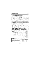
Set the node address of the inverter on the Profibus network.
Set the inverter node address before switching on the inverter and do not
change the setting while power is on.
The node address may be set between 0
H
and 7D
H
.
With input power on, do not install or remove the option unit.
Otherwise, the inverter and option unit may be damaged.
CAUTION
1. Do not set the node address to 7E
H
through FF
H
.
2. Depending on the master module, 0
H
, 1
H
, 2
H
, 7C
H
, 7D
H
may not
be used.
3. The node address changed while powering on the inverter is not
made valid. The node address setting is made valid either after
power is reapplied or when the RES signal turns on.
4. You cannot set the same node address to other devices on the
network. (Such setting disables normal communication.)
$
Set the arrow (
%
) of the corresponding switch to the
required numeral.
Example:
•For node address 1
H
:
Set (
%
) of SW1 to "0" and (
%
) of SW2 to "1".
•For node address 7D
H
:
Set (
%
) SW1 to "7" and the (
%
) SW2 to "D".
REMARKS
Set each node address switch to the
position of its numeral without error. If it is
set to any position between numerals,
normal data communication cannot be
made.
CAUTION
0
1
23
4
5
678
9 A
BC
D
EF
0
123
4
56
7 89
AB
C
D
EF
SW2
SW1
0
123
4
5
67
8 9
AB
C
D
EF
0
1
23
4
56
7 89
AB
C
D
EF
SW2
SW1
012
34
5
67
89A
BC
D
EF
012
34
5
67
89A
BC
D
EF
Bad example
Good example


