background image


Notebook Maintenance 

    4-3

?

 If the battery pack has been left unused for a long period of 

time, or if the battery has deteriorated, the remaining battery 
capacity may bot be displayed accurately. Recommend a 
process of fully charging, discharging, and then charging. It 
can take several hours. If still not recover yet, call near service 
centers. 

?

 The battery pack is a consumable item. After a certain perion 

of time  when the computer runs off within dramatically short 
time and needs repeatedly recharging or does not restore its 
performance, the battery pack should be replaced with a new 
one. 

4-3.2 The Battery Pack Guidelines 


?

  Battery pack should protected as below- 

    To avoid the possibilitiy of overheatm fire or drop damage. 
    To avoid extreme heat, cold and direct sunlight. 
    Do not use with any other computer. 
    Do not put into a microwave. 
    Do not expose the battery pack to water, or allow it become wet. 

Do not place battery pack together with articles, such as necklaces or 
hairpins when carrying or storing. 

?

 Recharge the battery pack when it is nearly discharged. When 

 recharging, make sure the battery pack is fully charged. 
 Doing so may avoid harm to the battery pack. 

Summary of Contents for A770

Page 1: ...A770 ENHANCE SERIES NOTEBOOK OPERATOR S MANUAL MITAC Technology Corporation P N 799001180012 R00 ...

Page 2: ......

Page 3: ...te and reliable as of the printing date MTC Corporation reserves the right to make changes to this manual or product specifications without obligation to notify any person of such changes IBM IBM PC AT and OS 2 are registered trademarks of International Business Machines Corporation Intel Pentium is a registered trademark of Intel Corporation MS DOS Windows 2000 Windows XP are registered trademark...

Page 4: ...icular installation If this equipment does cause harmful interference to radio or television reception which can be determined by turning the equipment off and on the user is encouraged to try to correct the interference by one or more of the following measures Reorient or relocate the receiving antenna Increase the separation between the equipment and receiver Connect the equipment into an outlet...

Page 5: ... and may not comply with FCC RF exposure requirements This equipment complies with FCC radiation exposure limits set forth for an uncontrolled environement This equipment must be installed and operated in accordance with provided instructions and minimum 20 cm spacing must be provided between antenna and all person s body excluding extremities of hands wrist and feet during wireless modes of opera...

Page 6: ...rms EN50081 1 Electromagnetic compatibility Generic emmision standard EN55022 conducted Emission Radiated Emission EN61000 3 2 Current Harmonic EN61000 3 3 Voltage Flicker EN50082 2 Electromagnetic compatibility Generic immunity standard IEC1000 4 2 Electrostatic Discharge IEC1000 4 3 Radiated Susceptibility IEC1000 4 4 Electrical Fast Transients IEC1000 4 5 Surge Test IEC1000 4 6 Conducted Suscep...

Page 7: ...e Record of Changes CHANGE NO DATE TITLE OR BRIEF DESCRIPTION ENTERED BY 00 06 Oct 2003 Initial Release 01 14 June 2004 Add section 3 2 6 ...

Page 8: ... on the hard disk supply information about any software included with the system Audience All operators using the notebook in or out of the field should read and become familiar with this manual Organization This manual has four chapters Chapter 1 introduces the notebook pointing out its major features Chapter 2 explains daily operation Chapter 3 gives detailed information about configuring the no...

Page 9: ...ve Keyboard 87 key shower proof and dust proof rubber keyboard Embedded two button Track Pad LED Backlight Rubber Keyboard Point Device A toucn senstive control pad with Microsoft Win Mouse function coexist support Glove hand Touch Pad Bay 1 Modules Swappable for CD ROM DVD DVD RW FDD Battery 2nd HDD COMBO drive Bay 2 Modules 2nd PCMCIA Removable Type III x 1 or TYPE II x 2 Module COM port Module ...

Page 10: ... 1394 port Mic In and Line Out Battery pack Removable rechargeable main Li ion battery pack with the functions of on line charge and hot swap Primary battery pack 97 watts Removable rechargeable Bay 1 Li ion battery pack in Bay 1 total 65 watts Removable rechargeable Bay 2 Li ion battery pack in Bay 2 total 65 watts Power adapter I P AC 100 240 V 50 60 Hz O P DC 19V 5 4 74A 90W CV mode 9 12 VDC di...

Page 11: ...i Open Size With Rubber Bumper 315mm W 70mm H 260mm D Weight 14 3 lbs 6 5 kg ...

Page 12: ... are out of traffic and unobstructed by personnel or equipment 9 Avoid using extension cords with this product If an extension cord is needed make sure it is rated for at least 10 amperes 10 Make sure amperage drawn by all items plugged into an outlet with this system does not exceed 15 amperes 11 Do not put any objects except those designed for use with this system inside the computer 12 Observe ...

Page 13: ...ions f Safety Summary Safety Summary h Chapter 1 System Overview 1 1 Introduction 1 1 1 2 System Description 1 1 1 3 System Configuration 1 1 1 3 1 Standard Configuration 1 1 1 3 2 Options and Accessories 1 3 1 3 3 System Identification 1 4 1 4 Unpacking 1 4 1 5 Notebook Features 1 5 1 5 1 Feature Description 1 8 ...

Page 14: ...e PCMCIA FDD CD ROM DVD COMBO DVD RW 2 4 2 3 Connecting and Installing Devices 2 4 2 3 1 Serial and Parallel Port 2 4 2 3 2 External Power Adapter 2 5 2 3 3 Floppy Disk Drive CD ROM DVD COMBO DVD RW 2 6 2 3 4 Loading and Remoce Diskette 2 8 2 3 5 PCMCIA Cards 2 8 2 3 6 Remove the Hard Disk Module 2 9 2 3 7 IEEE 1394 2 10 2 3 8 EMI Accessory Descriptions 2 11 2 4 First Time Use 2 13 2 4 1 Installin...

Page 15: ...iii 2 4 5 Wireless LAN Utility Installation PROSET 2 18 ...

Page 16: ...24 Chapter 3 The SETUP Program 3 1 Introduction 3 1 3 2 Running SETUP and Moving Around 3 1 3 2 1 Main 3 2 3 2 2 Moving Around and making Selections 3 3 3 2 3 Security Menu 3 11 3 2 4 Boot Menu 3 15 3 2 5 Exit Menu 3 16 3 2 6 How to Release Resource from SCU 3 17 Chapter 4 Notebook Maintenance 4 1 Introduction 4 1 4 2 Daily Use 4 1 4 3 Battery Maintenance 4 1 4 3 1 Conserving Power 4 1 4 3 2 Chang...

Page 17: ...v 4 4 Cleaning 4 2 ...

Page 18: ... 22 Figure 1 10 Diskette Drive and CD ROM DVD COMBO DVD RW 1 26 Figure 2 1 Opening the Notebook 2 2 Figure 2 2 Opening a Door 2 3 Figure 2 3 Connecting the External Power Serial Parallel Ports 2 4 Figure 2 4 Connecting the External Power Adapter 2 5 Figure 2 5 Removing a FDD CD ROM DVD COMBO DVD RW Module 2 7 Figure 2 6 Removing a Diskette 2 8 Figure 2 7 Removing a PCMCIA Cards 2 9 Figure 2 8 Remo...

Page 19: ...vii List of Tables Table 1 1 Standard A770 Notebook Computer 1 2 ...

Page 20: ...viii ...

Page 21: ...Processor 1 6GHz Dothan 1 8GHz CPU is the heart of this notebook computer This chapter introduces and explains the A770 notebook and its computer parts 1 2 System Description The A770 computer is a compact fully portable notebook computer It operates as a stand alone system for most applications It offers superior performance under harsh environmental and operating conditions It is fully compatibl...

Page 22: ...e Transflective LCD Battery Primary Li ion Type Battery life for 5 hours Bay1 Li Ion Smart Battery Bay2 Li Ion Smart Battery Keyboard 87key shower proof rubber keyboard Embedded two button track pad Optional LED Backlight Rubber Keyboard Expansion Two PCMCIA sockets type II or one type III compatible I O Devices One RS 232 serial port One Centronics parallel port support EPP ECP One VGA monitor po...

Page 23: ...GPRS or CDMA GPS Module Optional singly 2nd PCMCIA Removable TYPE III x 1 or TYPE II x 2 Module DGPS DGPS Module Bay2 Battery Pack Removable and Rechargeable Li lon Battery Pack SCSI Module 10 100 1000 Base T LAN 1 3 2 1 Carrying Bag The carrying bagmakes carrying the notebook andits peripherals easier It has compartments for up to four diskettes this manual the power supply and all notebook cable...

Page 24: ...ok It contains Factory configuration Model number Serial number 1 4 Unpacking Usethischecklisttomakesureallitemsincluded with thenotebook are present in good condition Notebook computer Rechargeable battery pack AC adapter Power cord User s Manual CD Driver If any items are missing or damaged please contact the supplier ...

Page 25: ...t stated and become familiar with your A770 Some of the features described in this section might vary from your individual A770 due to the different configuration and optional items available Figure 1 1 Features of the A770 1 Wireless modem antenna 2 LED Status Singal 3 Sealed Keyboard 4 Sealed Access Doors 5 Flat Panel Display 6 On Off Switch 7 Touchpad Point Device 8 Stereo Speakers ...

Page 26: ...1 6 System Overview 9 Carring Handle 10 Opening Latch 11 LCD Rubber Bumpers Figure 1 2 Features of the A770 ...

Page 27: ... Door Rear Panel 13 Bay 2 Access Door 14 Removable Hard Disk Drive Module Access Door 15 Removable Primary Battery Access Door 16 Audio Jacks 17 PCMCIA CardBus Slots 18 Removable Floppy Disk Drive Bay 1 Figure 1 3 I O Access Door of the A770 ...

Page 28: ...glare 12 1 14 1 color flat panel display 6 On Off Switch This switch controls the power to the A770 7 Touchpad Point Device The keyboard is equipped with an embedded two button touchpad point device 8 Stereo Speakers The A770 is equipped with two stereo speakers for audio sound 9 Carrying Handle The durable carrying handle makes transportation of the A770 10 Opening Latch The A770 is equipped with...

Page 29: ...RemovablePrimary Battery The A770 is equipped with rechargeable and removable 97 Whr primary battery 16 Audio jacks Two audio jacks line out and mic in are provided on the A770 17 PCMCIA CardBus slots The A770 provides two Type II or one Type III PCMCIA CardBus slots for added expansion 18 Removable Floppy Disk Drive Module The A770 is equipped with removable 3 5 1 44 MB floppy disk drive module 1...

Page 30: ...tick and more 3 PortReplicator Port The Port Replicator Port is an 80 pin interface expand two USB2 0 PIO VGA port 4 RJ 45 Port Connects the LAN cable 5 RJ 11 Port Connects the telephone line 6 VGA Port Connects the Externial monitor 7 Printer Port Connects a parallel device such as a printer 8 Serial Port Connects a serial device such as a serial modem mouse etc Figure 1 4 Keyboard Key Function ...

Page 31: ... keys It eliminates the need for external mouse device The touchpad is pressure senstive and works by the touch and movement of your fingertip Smoothly move your fingertip over the pad in the direction in which you want the cursor to move Refer to the tables on the following pages for the main functions of the keyboard keys and helpful tips on use of the embedded touchpad Figure 1 5 Keyboard with ...

Page 32: ...ck This key switches the number pad between acting as unmeric keys or editing keys When the keyboard Num Lock indicator is lit the number pad is active 5 Prt SC Sys Req Sends the information currently showing on the display to a connected printer Pressing this key in conjunction with the Ctrl key sends all output to a connected printer Press this key combination again to stop the function 6 Back S...

Page 33: ... s manual for a particular application program to determine the function of each of these keys To use a Ctrl key combination hold down the Ctrl key and the other key simultaneously 12 Windows One of two Windows key provided on the A770 The Windows logo key is used in conjunction with other keys to perform software specific functions 13 14 Alt The A770 provides two Alt keys Works in conjunction wit...

Page 34: ...lication program you are using it lets you scroll to the next page 20 Arrows The four direction arrow keys control the movement of the cursor on the screen They do not affect the displayed character keys 21 Del Delects the character to the right of the cursor All remaining characters to the right move one space to the left 22 Ins Places the keyboard into the insert mode While in the insert mode da...

Page 35: ...System Overview 1 15 Figure 1 6 Cursor Control Keys ...

Page 36: ...r to go To Click Press the touchpad s left or right button or lightly tap on the touchpad To double click Either press the button twice or lightly tap the touchpad twice in quick succession There are two ways to drag Move the cursor to the desired location the press down the left button While still holding down the left button move the cursor to the desired location Then release the button Move th...

Page 37: ... using the DOS program Brightness Control The brightness control is adjusted by use of a combination of function keys Press the Fn F5 keys to darken the screen image Press the Fn F6 keys to brighten the screen image To further adjust the screen image press and hold down the Fn key and continue to repeatedly press either the F5 key or the F6 key until you obtain the desired brightness If you presst...

Page 38: ...3 Suspend to RAM S4 Suspend to Disk then the LCD Backlight always on 1 5 4 1 Hot Key Function Keys Feature Description Fn F3 Volume Down Descrease the volume Fn F4 Volume Up Increase the volume Fn F5 Brightness Down Decreases the LCD brightness Fn F6 Brightness Up Increases the LCD brightness Fn F8 Keyboard Backlight Switches the keyboard backlight On Off Fn F9 LCD External CRT Switching Switches ...

Page 39: ...nly upper case text when you press the keys Num Lock This light indicates that the keyboard in in the Num Lock mode This key activities and de activates the embedded numeric keypad provided on the keyboard HDD FDD CD The Orange HDD light indicates that the system is accessing the hard disk drive The orange FDD light indicates that the system is accessing the floppy disk drive And the orange CD lig...

Page 40: ... as frequency as possible 1 5 4 3 Status Row The Status Row Figure 1 8 keeps you informed of the computer s operating status The LEDs light up show the current operating condition of several key A770 devices and features See Fig 1 8 1 When the power is on then Power LED Green is on 2 When the AC power adaptor is connected then the AC IN LED Green is on in power stage When charging is in progress t...

Page 41: ...reen without the top bottom or any lines in between moving Battery Pack The removable battery pack with on line charge capability comes standard with the A770 The battery pack provides power to the system when the AC power is Off or not connected It has a 97whr capacity operate The primary battery type is Li ion At 4 2V the battery pack consists of twelve cells The capacity of each cell is 2200 mA...

Page 42: ...tery pack in the A770 can be charged during both the power On and Off stages Two charge mode are provided when the AC power adapter is connected to the system When the power is Off a fast charge mode is activated with a constant current for the primary battery pack The charge time for the primary battery pack is about 3 5 4 hours When the power is On an alternate charge mode is activated for the p...

Page 43: ...he orange CHARGE LED remins is Off Connections To expend your computing capabilities the A770 is equipped with several interface ports and connection receptacles These connectors support a variety of external peripheral devices Serial Port The A770 includes one standard 9 pin D type RS 232C serial port for connecting a serial mouse or other external serial devices The D type connector is dedicated...

Page 44: ... Port The A770 provides a USB2 0 Universal Serial Bus port for connecting USB compliant devices Most peripheral devices require the user to shutdown the system plug in the device and restart the system in order to use the new device USB devices can be conveniently connected and disconnected while the system is running The USB port transfers data at 480 MB sec Please refer to the device specific do...

Page 45: ...wer to the A770 The power port is located on the rear panel of the A770 IEEE 1394 Port The A770 provides a standard IEEE 1394 port for high speed connections The High Speed Serial Bus is located on the right side panel next to the audio jacks Audio Connecitons The A770 comes standard with two speakers and two audio hook up jacks The jacks are located on the right side of the A770 adjacent to the P...

Page 46: ...n auxiliary battery 65whr The batteries can be hot swapped CAUTION Use only the battery pack indicated in this manual Do not dispose of batteries in a fire They may explode Check with local codes for possible special disposal instructions NOTES Recommend always charge the battery pack with the computer powered off Do not charge the battery repeatedly before it is discharged completely Recharge the...

Page 47: ... compact transferable media Data stored on diskettes can be easily passed from one machine to another The A770 Series diskette drive accepts 3 5 double density 720 KB and high density 1 44 MB diskettes 1 5 6 1 PCMCIA Slot and Diskette Drive and CD ROM DVD COMBO DVD RW Door The PCMCIA slot and diskette drive and CD ROM DVD COMBO DVD RW door Item 1 Figure 1 10 protects the PCMCIA interfaces and disk...

Page 48: ...tery pack This chapter will cover the operation of the A770 The A770 supports a wide range of external peripheral devices Installation instructions and procedures for these devices will also be covered in this chapter The A770 provides two compartment bays for optional removable device modules and PCMCIA CardBus slots for add in expansion 2 2 Opening and Closing the Notebook This section provides ...

Page 49: ...e viewing angle Usually about 110 See Figure 2 1 2 2 2 Closing the Cover Be sure to turn the system Off and disconnect the power before closing the cover If not the system will stay On when you close the cover Push the cover down until it clicks shut Push in on the latch to secure it Figure 2 1 Opening the Notebook ...

Page 50: ...d screwdriver or the edge of a small coin into the slot of one of the cptive screws securing the access door 2 Turn the screw counter clockwise until it comes loose from its socket 3 Repeat steps 1 and 2 for each screw securing the access door 4 Use the handle to open the access door If the access door does not have a hanele use one of the loosened screws to pull open the door Figure 2 2 Opening a...

Page 51: ...ling Devices This section gives instructions for installing removing changing or connecting devices via the notebook external ports or sockets 2 3 1 Serial and Parallel Port Use the Serial port to connect a serial device and the Parallel port to connect a parallel device usually a printer or an external floppy disk drive into the A770 I tem 1 Item2 Figure 2 3 shows how to connect serial and parall...

Page 52: ...ure 2 3 shows how to connect the power adapter Make sure the mating connector is tightly secured by pushing it to the end 1 Plug the connector from the AC adapter into external power port on the rear panel of the A770 See Fig 2 4 2 Now plug the power cord into the adapter 3 Plug the other end the power cord into a 3 prong wall outlet or power strip Figure 2 4 Connecting the External Power Adapter ...

Page 53: ... 4 cm 4 Pull the handle outwards about 3 cm Do not force it out any further as it might damage the unit 5 Using both hands gentlly slide the entire FDD CD ROM DVD COMBO DVD RW module out form the bay 1 compartment 2 3 3 1 Replace the FDD CD ROM DVD COMBO DVD RW Using both hands gentlly insert the FDD CD ROM DVD COMBO DVD RW module back into the bay 1 compartment Continue to slide it in unti it sea...

Page 54: ...Operation 2 7 Figure 2 5 Removing a FDD CD ROM DVD COMBO DVD RW Module ...

Page 55: ...CardBus slots support two type II or one type III PC card Since both type II slots are co located in the same opening one type III PC card can be inserted instead of two type II PC cards The type III PC card occupies both slots The A770 supports hot insertion You can insert the PC card into the slot while the system is powered On 1 Open the PCMCIA slot diskette drive door 2 Slide the card into the...

Page 56: ...A770 Off 2 Loosen the captive screws securing the access door 3 Use the handle on the access door to carefully pull the HDD module out and away from the A770 See Fig 2 8 4 Insert the new Hard module into the slot Gently push the HDD module in until it seats firmly in place Secure the captive screws on the access door Turn the power back On to the A770 Figure 2 7 Removing a PCMCIA Cards PCMCIA Card...

Page 57: ... and Compatible with Proposal 1394A 3 3V Core Logic with Universal PCI Interface Compatible With 3 3V and 5V PCI Signaling Environments Compliant to Latest PCI Specification PCI 2 2 PCI Power Management Compliant c Cable Power Presence Monitoring Low Cost 24 576MHz Crystal Provides Transmit Receive Data at 100 200 400 Megabits per Second and Link Layer Controller Clock at 49 152 MHz Fully Interope...

Page 58: ...re are one same EMI cores One is used to directly wrap around the 1394 cable of the user near the 1394 port side NOTE The cores should be put close to the computer side for best performance 2 EMI Cable There are two same EMI cables One is for the microphone port and the other is for the speaker port The male connectors are connected to the microphone and speaker ports and the female connectors are...

Page 59: ... core is used for the modem port NOTE The connector close to the EMI core should be connected to the modem port of the computer for best performance EMI Cable Figure 2 10 EMI Core Cable EMI Core Speaker Port Microphone Port 1394 Cable Picture sample only not included ...

Page 60: ...or from the AC adapter into the external power port on the rear panel of the A770 Now plug the power cord into the adapter 3 Plug the other end of the power cord into grounded 3 prong wall outlet of power strip 4 Turn On the A770 2 4 1 Installing Software Drivers To take full advantage of the unique features of your computer some operating systems require custom software known as drivers to be ins...

Page 61: ... driver CD supports Windows 2000 and Windows XP only The available items may differ according to your computer model and Operating System Note If driver CD version is not the same as the one shown on the Operation Manual please refer to the UserGuide file on the driver CD for the latest driver installation action steps and sequence 2 4 2 Install Device Driver for Windows 2000 Windows XP To install...

Page 62: ...mation over a standard telephone line through RJ 11 port Speedstep Press the Speedstep button the system will auto install for Window 2000 LAN Wireless LAN Allows you to use the network function of the computer USB 2 0 Allows your system to connect to USB 2 0 devices DirectX 8 1 Allows you to take full advantage of the multimedia applications Chipset Ensures the full function of the following driv...

Page 63: ... The driver should now be loaded 4 After the system has finished rebooting click on the PenMount Monitor icon located on the taskbar to bring up the PenMount Control Panel 5 Select the Standard Calibration folder and click on OK button 6 If you need 4 9 16 25 dot of the calibrate we suggest select Advanced Calibration button to calibrate 7 Click on the four sides points and the plus sign on the sc...

Page 64: ...talling Touch PAD Driver 1 Insert the driver CD into the drive 2 Upon clicking on the TouchPAD link on the main screen the Installation Wizard appears on screen Upon clicking on Next the following screen appears as shown next ...

Page 65: ...Operation 2 18 2 4 5 Install Touch Screen Driver for Windows XP Hardware Install 1 Insert the driver CD to the CD drive to bring up the following screen Select WINXP ...

Page 66: ...Operation 2 19 2 When the TSRC XP htm file appear then select START Control Panel button ...

Page 67: ...Operation 2 20 3 When the Control Panel screen appear then click on performance and Maintenance button ...

Page 68: ...Operation 2 21 4 When the Performance and Maintenance screen appear and then click on System button ...

Page 69: ...Operation 2 22 5 When the System Properties screen appear and then click on Hardware and Device Manager button ...

Page 70: ...Operation 2 23 6 When the Device Manager screen appear then click on Unknown device and then click on the Properties icon ...

Page 71: ...Operation 2 24 7 When the Unknown Device Properties screen appear and then click on Reinstall Driver button ...

Page 72: ...Operation 2 25 8 When the Hardware Update Wizard appears click on Install the software automatically Recommand then click on Next 9 When the Hardware Installation screen appears click on Continue Anyway ...

Page 73: ...Operation 2 26 10 When the Hardware Update Wizard screen appears click on Finish button ...

Page 74: ...Operation 2 27 11 When the PenMount DMC9000 and DMC9100 Properties screen appears click on Close button to exit the driver installation ...

Page 75: ...orm the following 1 Insert the driver CD to the CD drive to bring up the following screen 2 Click on Start then Run 3 Enter the following directory on the driver CD TOUCHSCREEN Setup exe then click on OK 4 Select Yes to the question if this is the first time to run this setup ...

Page 76: ...Ready to Install the Program screen appears clcik on Install to continue 8 Reboot the system 9 After the system has restarted click on the PM icon located on the lower right portion of your taskbar to bring up the PENMOUNT Control Panel 10 When the PENMOUNT Control Panel dialog box appears click on the Calibrate folder and click on the Standard Calibration button ...

Page 77: ... external power make sure it is connected 3 Open the cover 4 Press the Power button The power on indicator lights up The computer performs a Power On Self Test POST and checks configuration settings Depending on the configuration items tested include system board system DRAM video controller keyboard controller I O controllers hard disk diskette drive 5 If the POST finds an inconsistency between e...

Page 78: ...ebook 1 Save all data and close all open programs 2 Press the Power button to turn off power 3 Swing the cover closed until it clicks shut 4 Turn off and disconnect all peripheral devices 5 Close and tighten all access doors and covers 2 5 3 Using the Notebook in the Car When you using the notebook in the car you must carefully follow as 1 Start engine wait five to ten minutes and then plug car po...

Page 79: ... the following constraints A Series AC 100 240 V 50 60 Hz DC 9 19 5 VDC direct input without charging function option 12 32 VDC external car adapter charger option Connecting to sources outside this range may damage the external power adapter Figure 2 11 Plug Car Power Cable in Notebook Plug in car cigarette lighter ...

Page 80: ...hich shows the batteries are running out of energy please connect the adapter to the computer and plug in the power cord to the outlet immediately 2 6 2 Charging the Batteries Make sure the external adapter is connected to the computer It has two charging rates depending on notebook operating or power off Section 2 6 1 gives detailed instructions on connecting an external power source and charging...

Page 81: ...veral power management features to prolong continuous operation on batterypower This section describes the power saving modes and tells how to take best advantage of them It includes default settings for each mode For instructions about changing them see chapter 3 ...

Page 82: ... the amount of memory special features include Power Saving and Security The configuration information is stored in a special kind of memory called CMOS Complementary Metal Oxide Semiconductor RAM A RTC backup battery backs up CMOS RAM data You may need to run SCU when You see an error message on the screen requesting you to run SETUP You change factory default settings for some special features Y...

Page 83: ...s F2 quickly The SCU menu appears as shown next 3 2 1 Main This section describes the main items of the SETUP program The SCU screen can be divided into four areas On the top line of the screen is the menu bar which lists the titles of the available menus Each menu title contains a pull down menu which displays items for setting The left column of the screen displays the current configuration info...

Page 84: ...ion Selects a menu title Selects an item or option Enter Opens or closes the options window when an item is selected Space bar Cycles through the pre defined value for the selected item Pressing the space bar brings up the next value pressing the minus key does the contrary Esc 1 Exits the SCU program 2 Returns to the previous menu if in a submenu 3 Closes the options window if one is open NOTE Yo...

Page 85: ... system Select the Main category from the menu bar if you wish to change these settings A description is provided for each option listed on the pull down menu Date and Time The Date and Time option allows you to reset the current date and time for your system When this option is selected the submenu will displayed as show below ...

Page 86: ... anumemckey without Fn pressed When disabled the Internal Numlock of the BIOS setup then turn on the Num lock on keyboard internal keyboard is not available for entering but external ones A check mark indicatesEnabled anunderline _ indicatesDisabled The default setting is Disabled USB Emulation Enables or disables the USB devices in DOS mode The default setting is Enabled ...

Page 87: ...When the LED Keyboard Backlight need dark at power on status then select the Keyboard Backlight setting is Disable The Fn F8 function can toggle Backlight of the keyboard light or dark but Fn F8 can t effect the CMOS Setup of the Keyboard Backligt item Primary HDD Heater Set Primary HDD Heater function Enable Disable detail information see the HDD Heater User Guide ...

Page 88: ...SetupConfiguration Utility 3 7 Mini PCI Card To enable or disable Mini PCI slot function this function is secure security protection when this machine enquiped with WLAN card on Mini PCI slot ...

Page 89: ...Geyserville feature of the CPU The Geyserville feature helps conserve battery life by decreasing the CPU s running speed undercertainconditionswhilestillmaintainingahighperformance Ifthisitem is enabled the CPU will automatically change its speed whenever necessary based on the Power Scheme setting in Windows s Control Panel If this item is disabled the CPU will always run in the lowest speed ...

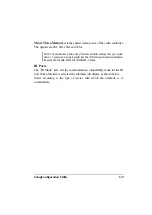
Page 90: ...will depend on your system memory If you system memory is greater than 256 512 MB system will automatically set the above item to 64MB When WinXP Win2000 is loaded IR Ports The IR Mode item sets the communications compatibility mode for the IR port When this item is selected the submenu will display as shown below Select according to the type of device with which the notebook is to communicate ...

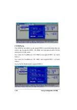
Page 91: ...unctions that you wish to use In general COM1 3F8 IRQ4 can be assigned to RS 232 the serial port or touch screen User select the TouchScreen 3E8 IRQ5 was assigned COM 3 to Touch Screen User select the TouchScreen 2F8 IRQ3 was assigned COM 3 to Touch Screen User select the Disabled was assigned COM 4 ...

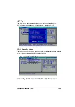
Page 92: ... parallel port When this item is selected the submenu displays as shown below 3 2 3 Security Menu The Security pull down menu as shown below contains the Security settings that safeguard your system against unauthorized use The followings describe in sequence all the items of the Security menu ...

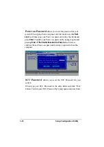
Page 93: ...ntry fields and press Enter Confirm your Power on password by typing it again and pressing Enter If the Enable Password to Power on sub item is enabled the set Power on password is always required to boot the computer SCU Password allows you to set the SCU Password for your system When type your SCU Password in the entry fields and click OK button Confirm your SCU Password by typing again and pres...

Page 94: ...p Scu Password completed after if your save change and exit system will let your type again If the Enable SCU Password sub item is enabled When use the SCU Password must in two condition one is enter SCU and the other in Exit Save changes and Exit ...

Page 95: ... hard disk boot sector partition table has been changed A check mark indicates enabled while anunderline _ indicates disabled The default setting is disabled CAUTION sets this item to disabled before installing an operating system running Fdisk or Format program Otherwise the intended action will fail ...

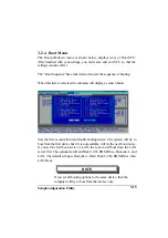
Page 96: ...ill display as shown below Sets the first second third and fourth booting device The system will try to boot from the first device but if it is not available will try the next boot device If you set the first boot device to LAN the system will boot from the LAN server first The optionals are Hard Disk C CD ROM Drive Diskette A and LAN The default setting is Diskette A Hard Disk C CD ROM Drive then...

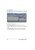
Page 97: ...st save and exit SCU so that the settings can take effect Descriptions of the Exit choices are 1 Save Change and Exit Save changes you have made and exit 2 Discard Changes and Exit Exit without saving the changes you has made 3 Get Default Values Load factory default values for all the items 4 Load Previous Values Restore previous values for all the items ...

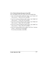
Page 98: ...U Advanced COM Ports COM1 Settings select Disable will release resource IO port 3F8h 3FFh and IRQ4 3 Under SCU Advanced COM Ports COM3 Settings select Disable will release resource IO port 3E8h 3FFh and IRQ5 4 Under SCU Advanced COM Ports COM4 Settings select Disable will release resource IO port 2E8h 2FFh and IRQ11 5 Under SCU Advanced LPT Port Port Address select None will release resource IO po...

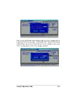
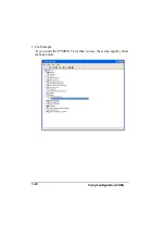
Page 99: ...SetupConfiguration Utility 3 18 1 For Example If you insert the PCMCIA Card then you see the screen appear yellow mark as below ...

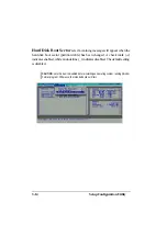
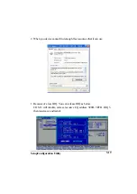
Page 100: ...ility 3 19 2 When you device cannot find enough free resources that it can use 1 Because of a less IRQ You can release IRQ as below COM 3 will disable release resource I Q address 3E8H 3EFH IRQ 5 then must save and restart ...

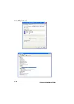
Page 101: ...SetupConfiguration Utility 3 20 4 Use IRQ5 as below ...

Page 102: ...o maximize the battery life Use the lowest brightness and contrast display settings Avoid using reverse video The white text on a black background uses significantly less power than black on white Spme screen savers place a large burden on the CPU We recommend that you do not use screen saver programs Develop good consistent work habits Set the power management features according to your style For...

Page 103: ...diately flush eyes with clear weater and see a doctor as soon as possible NOTE Take off the battery pack within computer when it is not used If the battery pack will not be used in the term of 10 deys or l onger period please charger or discharge the battery pack to maintain 30 to 40 battery level and store it in cool dey room If you remove the battery pack make sure the battery terminals do not c...

Page 104: ...epeatedly recharging or does not restore its performance the battery pack should be replaced with a new one 4 3 2 The Battery Pack Guidelines Battery pack should protected as below To avoid the possibilitiy of overheatm fire or drop damage To avoid extreme heat cold and direct sunlight Do not use with any other computer Do not put into a microwave Do not expose the battery pack to water or allow i...

Page 105: ...carry the computer Do not check it in as luggage Allow extra time for airport security Many airports inspect electronic devices carefully If you need to leave the computer in the car put it in the trunk of the car to avoid exposing the computer to excessive heat When going through airport security it is recommended that you send the computer and floppy disks through the X ray machine the device yo...

Page 106: ... ischarging and then charging It can take several hours 1 Make sure the computer power is turned off Connect the AC adapter to fully charge the battery pack 2 After the battery pack is fully charged turn on the computer into SCU or disable power management in Windows 3 Disconnect the AC adapter and leave the computer in until the battery is fully discharged The computer will shut down antomaticall...

Page 107: ... Maintenance 4 6 4 4 Cleaning Periodically clean the exposed notebook surfaces Use a soft cloth and water or mild detergent to clean all surfaces The glass cleaner is recommended for cleaning the display screen ...

Reviews: