background image

2-11

Setting-up

Setting-up

Chapter 2

3

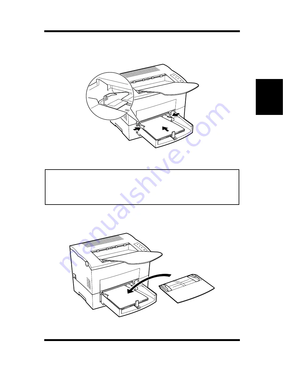
Place the paper stack onto the tray, print-side up. Secure the stack 
by adjusting the paper size guides.

Note

4

Replace the tray cover onto Tray 1.

• A maximum level mark on the paper size guide shows how high you 

can stack paper on Tray 1. Make sure that paper is stacked no higher 
than this mark.

• See pages 4-56 and 5-7 for details on making settings for Tray 1.

Summary of Contents for PageWorks 18

Page 1: ...User s Manual PageWorks 18...

Page 2: ...the ENERGY STAR Guidelines for energy efficiency What is an ENERGY STAR Printer ENERGY STAR printers have a feature that allows them to automatically go to sleep after a period of inactivity This auto...

Page 3: ...int head unit The print head unit is NOT A FIELD SERVICE ITEM Therefore the print head unit should not be opened under any circum stance Laser Safety This printer is certified as a Class 1 Laser produ...

Page 4: ...ontrols adjustments or performance of procedures other than those specified in this manual may result in hazardous radia tion exposure This is a semiconductor laser The maximum power of the laser diod...

Page 5: ...to try to correct the interface by one or more of the follow ing measures Reorient or relocate the receiving antenna Increase the separation between the equipment and the receiver Connect the equipme...

Page 6: ...rm to FCC regulations and any changes or modifications must be registered with the FCC and are subject to FCC control Any changes made by the purchaser or user without first contacting the manufacture...

Page 7: ...is released This amount is not large enough to harm anyone adversely However be sure the room where the machine is being used has adequate ventila tion especially if you are printing a high volume of...

Page 8: ...languages without the express written prior consent of Minolta Co Ltd The contents of this manual are subject to change without notice Trademark Acknowledgments PCL is a registered trademark of Hewlet...

Page 9: ...uestions and handles all e mail requests for technical assistance at http www minoltaprinters com Please be prepared to provide the following information when contact ing Minolta Technical Support Mod...

Page 10: ...Lights 1 4 Control Panel Button 1 8 Job Cancel 1 8 Print Configuration 1 8 Form Feed 1 8 Chapter 2 Setting up Installation Precautions 2 1 Selecting a Location for the Printer 2 1 Power Source 2 2 Gro...

Page 11: ...2 15 Options 2 16 SIMM Single In line Memory Module 2 16 Installing the Optional SIMM 2 16 Duplex Unit 2 21 Installing the Duplex Unit 2 21 Second Third Paper Cassette Unit 2 24 Installing the Optiona...

Page 12: ...onto Tray 1 3 4 Loading Paper onto Tray 2 Tray 3 3 7 Manual Paper Feed 3 11 Printing on Envelopes 3 13 Duplex Printing 3 15 Paper Type 3 16 Paper Size 3 16 Chapter 4 Printer Driver Introduction 4 1 S...

Page 13: ...inter Driver 4 16 To Uninstall the Printer Driver 4 19 Displaying the Driver Setup Dialog Windows 95 98 NT 4 0 4 21 To Display the Driver Setup Dialog Under Windows 95 98 4 21 To Display the Driver Se...

Page 14: ...om Memory 4 51 Accessing the Printer Control Panel 4 52 To Access the Printer Control Panel 4 52 To Exit the Printer Control Panel 4 52 Using the Printer Control Panel 4 53 Getting Around in the Print...

Page 15: ...Menu 4 64 Close button 4 65 Help button 4 65 Chapter 5 Printer Status Display and Control Panel Using the Printer Status Display 5 1 Opening the Printer Status Display 5 1 To Open the Printer Status D...

Page 16: ...ace the Imaging Cartridge 6 2 Cleaning the Printer 6 6 Cleaning the Outside of the Printer 6 6 Cleaning the Paper Transport Roller 6 7 Chapter 7 Troubleshooting Technical Support 7 1 Clearing a Paper...

Page 17: ...Blurred background 7 12 Uneven print density 7 12 Irregularities 7 12 White or black line 7 13 Toner smudges 7 13 No output 7 14 Are you using the correct type of printer cable 7 14 Are your computer...

Page 18: ...xvi Contents Interface Connector and Cable 8 7 SIMM Option 8 8 Appendix A Glossary Appendix B Index...

Page 19: ...Chapter Introduction 1 Introduction Chapter 1...

Page 20: ...Introduction Chapter 1...

Page 21: ...us features listed below make the Minolta PageWorks 18 the perfect printer for any size office Fast 18 page per minute printing speed PCL 6 support for faster more precise printing Supports two option...

Page 22: ...00 sheet multipurpose tray cassette unit second cassette Face down tray Control panel Manual feed tray Paper size guide Tray cover Cassette cover option Paper size guide Power Top cover release button...

Page 23: ...Printer Parts and Accessories 1 3 Introduction Chapter 1 Power cord socket Image transfer roller Imaging cartridge Top cover Fusing unit Parallel interface connector...

Page 24: ...er s status by checking the information that appears on your computer screen through the Status Monitor Indicator Lights Printer Status and Recommended Action Ready green Paper amber Error red On Off...

Page 25: ...ng On Data is currently being compressed because more data is being processed than can be managed by the amount of memory installed in your printer You may notice a difference in image quality when co...

Page 26: ...to be loaded manually Load the appropriate size of paper onto the manual feed tray and press the panel button Off Off On Cover is open Close the cover Off Blinking Off Paper misfeed Clear the paper mi...

Page 27: ...the problem persists contact Minolta Technical Support Blinking Off Blinking Engine error polygon scanner Turn the printer off and on again If the problem persists contact Minolta Technical Support B...

Page 28: ...cancel the current job 1 Hold down the control panel button for about five seconds 2 After all the indicator lights are lit release the control panel button to cancel the print job Print Configuration...

Page 29: ...Chapter Setting up 2 Setting up Chapter 2...

Page 30: ...Setting up Chapter 2...

Page 31: ...nia or other organic gases being generated in the area The power outlet you plan to connect to should be nearby and unobstructed Make sure that the printer is not exposed to direct sunlight Avoid area...

Page 32: ...oltage capacity specified for this printer Be sure to plug the power cord all the way into the outlet The outlet should be located near the printer and be easily accessible so you can unplug the power...

Page 33: ...nance When equipped with an optional third cassette unit 11 3 4 300 mm or more 29 1 2 746 mm or more 34 1 4 867 mm or more 6 150 mm or more 11 3 4 300 mm or more 23 1 2 600 mm or more 40 1 2 1 028 mm...

Page 34: ...lace flammable gasses liquids or objects that generate magnetic forces near the printer When unplugging the power cord always grasp the plug and never pull on the cord A damaged cord creates the dange...

Page 35: ...ds to spill on or near the printer Fire or electrical shock can occur should water or liquid come into contact with the printer Should liquid or any piece of metal accidently get inside the printer im...

Page 36: ...reas subjected to high humidity Areas subjected to large amounts of dust Keep paper that has been removed from its wrapper but not yet loaded onto the printer tray in a sealed plastic bag and store it...

Page 37: ...bend the face down tray inwards and insert one of its tabs into its holder on the upper portion of the printer Continue to bend the face down tray so that it curves enough for the second tab to fit i...

Page 38: ...ting up Chapter 2 Installing Tray 1 1 Using the left and right slots in the printer as guides gently push Tray 1 until it cannot be inserted any further as shown in the illustration 2 Attach the tray...

Page 39: ...pter 2 Connecting the Power Cord 1 Make sure that the printer s power switch is in the Off posi tion 2 Connect one end of the power cord that comes with the printer to the power cord socket Plug the o...

Page 40: ...2 10 Setting up Setting up Chapter 2 Loading Paper 1 Remove the tray cover from Tray 1 2 Open all three paper size guides...

Page 41: ...he stack by adjusting the paper size guides Note 4 Replace the tray cover onto Tray 1 A maximum level mark on the paper size guide shows how high you can stack paper on Tray 1 Make sure that paper is...

Page 42: ...which indicates that the printer is warming up In about 23 seconds only the READY indicator remains lit indicating that the printer is ready to print Note The printer automatically enters a power sav...

Page 43: ...ration Page and see if the printer is working correctly 1 Place the paper onto Tray 1 2 Make sure that both the PAPER and ERROR indicators are off and the READY indicator is on This indicates there is...

Page 44: ...er 2 Sample Configuration Page Note See Chapter 7 of this manual for information on what to do if the Con figuration Page does not print when you press the panel button The Configuration Page can be p...

Page 45: ...are both turned off 2 Connect one end of the interface cable to the parallel port of the computer 3 Connect the other end of the cable to the parallel connector on the back of the printer Secure the...

Page 46: ...4 8 16 or 32 MB SIMM into one or both of the two memory connectors located inside of the printer Note Installing the Optional SIMM Warning 1 Turn off the printer and unplug the power cord 2 Disconnect...

Page 47: ...screws that secure the exterior side cover to the printer 5 Clips secure the exterior side cover from the inside of the printer Gently maneuver the exterior side cover until the clips release see ill...

Page 48: ...e exterior side cover removed the internal side cover of the printer is exposed With the screwdriver loosen and remove the four screws that secure the internal side cover 7 Remove the internal side co...

Page 49: ...oints along the edge of the SIMM insert the SIMM into one of the available sockets on the main circuit Insert the SIMM at an angle as shown and gently swing it into the socket Apply pressure until the...

Page 50: ...the Total Memory item correctly shows the increase in memory capacity If it does not repeat the above steps making sure that the SIMM is installed correctly Note To release the SIMM from the socket pu...

Page 51: ...f the paper through the printer software For more information refer to page 3 15 Take the duplex unit out of the shipping box Remove the plastic bag and all shipping materials Turn the printer off and...

Page 52: ...ign the L shaped duplex unit to the back of the main unit of the printer so that the bottom of the L is inside of the opening at the bottom of the printer Note Make sure that the connector of the unit...

Page 53: ...on See Connecting the Power Cord page 2 9 See Turning On the Printer page 2 12 5 Generate a configuration page to verify that duplex unit is listed under the Printer Configuration item See Testing the...

Page 54: ...e interchangeable and can increase paper holding capacity to 1 000 sheets when installed together Installing the Optional Second Third Paper Cassette Unit Take the paper cassette unit out of the shipp...

Page 55: ...et the printer onto the paper cassette unit using the coupling pins as a guide Note The printer weighs approximately 18 kg 39 7 lbs Two people are recommended to lift it when necessary Second paper ca...

Page 56: ...s Setting up Chapter 2 3 Insert Tray 2 or Tray 3 into the paper cassette unit Note Be sure to use both hands whenever Tray 2 or Tray 3 is being removed from or inserted into the paper cassette unit Tr...

Page 57: ...ord page 2 9 See Turning On the Printer page 2 12 5 Generate a configuration page to verify that Tray 2 or Tray 3 is listed under the Printer Configuration item See Testing the Printer page 2 13 PRINT...

Page 58: ...om the printer Installing the Optional Adobe PostScript ROM SIMM Warning 1 Turn off the printer and unplug the power cord 2 Disconnect the parallel cable from the printer 3 Press the top cover release...

Page 59: ...r the exterior side cover until the clips release see illustration Caution 6 With the exterior side cover removed the internal side cover of the printer is exposed With the screwdriver loosen and remo...

Page 60: ...g careful not to touch the connection points along the edge of the SIMM insert the SIMM into the socket of the main circuit Insert the SIMM at an angle as shown and gently swing it into the socket App...

Page 61: ...nd then turn the printer on See Connecting the Power Cord page 2 9 See Turning On the Printer page 2 12 12 Generate a configuration page to verify that PostScript is listed under the Printer Configura...

Page 62: ...2 32 Options Setting up Chapter 2 PRINTER CONFIGURATION Tray 2 Not Installed Tray 3 Not Installed Duplex Unit Not Installed PostScript Installed Network Card Not Installed...

Page 63: ...elect should be determined according to the requirements of your network environment For details please see the User s Manual for the Network Interface Card This illustration shows the optional 10 100...

Page 64: ...C out of its carton Note 4 Insert the NIC as shown in the diagram Make sure that you do not misplace the cover panel or screws when you remove them The screws will be used after the optional NIC is in...

Page 65: ...g the Power Cord page 2 9 See Turning On the Printer page 2 12 7 Generate a configuration page to verify that Network Card is listed under the Printer Configuration item See Testing the Printer page 2...

Page 66: ...MEMO Setting up Chapter 2...

Page 67: ...Chapter Using the Printer 3 Using the Printer Chapter 3...

Page 68: ...Using the Printer Chapter 3...

Page 69: ...m2 16 to 24 lbs Special Paper Recycled Paper weighing 60 to 90 g m2 16 to 24 lbs Trans parency Sheet Labels Letter head Enve lopes J Post Post card size 100 148 mm 4 5 3 4 Thick Paper weighing 90 to...

Page 70: ...inter Paper that is too thin or too thick Paper folded curled or torn Paper having binding holes or perforations Paper with surfaces that are too smooth or too rough or with varying surfaces Paper hav...

Page 71: ...ptional paper sources See the section of this User s Manual entitled Loading Paper onto Tray 2 Tray 3 for details on using these trays Whenever you are using special size paper be sure to use the prin...

Page 72: ...the Printer Chapter 3 Loading Paper onto Tray 1 You can load up to 250 sheets of standard paper onto Tray 1 See page 3 1 for details on paper sizes and types 1 Remove the tray cover from Tray 1 2 Ope...

Page 73: ...right sides of the paper stack are secure Note A maximum level mark on the paper size guide shows how high you can stack paper on Tray 1 Make sure that paper is stacked no higher than this mark Do no...

Page 74: ...3 6 Loading Paper Using the Printer Chapter 3 4 Replace the tray cover onto Tray 1...

Page 75: ...oving the Tray 2 Tray 3 cassette into and from the second third paper cassette unit refer to Chapter 2 The cassette is designed to remain in the unit during the normal loading and operation of the pri...

Page 76: ...3 8 Loading Paper Using the Printer Chapter 3 2 Remove the cassette cover from Tray 2 Tray 3 3 Press down on the paper lifting plate located inside of Tray 2 Tray 3 until it locks...

Page 77: ...s unwrapped is still facing up Note A maximum level mark inside the inlet of Tray 2 Tray 3 shows how high you can stack paper Make sure that paper is stacked no higher than this mark Tray 2 Tray 3 doe...

Page 78: ...3 10 Loading Paper Using the Printer Chapter 3 5 Replace the cassette cover and insert Tray 2 Tray 3 into the second third paper cassette unit Tray 2 Tray 3...

Page 79: ...the Printer Chapter 3 Manual Paper Feed 1 Make sure that the tray cover is properly attached to Tray 1 2 Open the paper size guides 3 Insert the sheet of paper into the manual feed tray with the side...

Page 80: ...12 Loading Paper Using the Printer Chapter 3 4 Adjust the paper size guides so that both sides of the paper are secure Note Insert only one sheet of paper or one envelope at a time when feeding manual...

Page 81: ...should be facing down and to the left 2 Make sure that the envelope is placed in the center of the tray and that it is secured by the paper size guides Note Note the following points whenever printing...

Page 82: ...ch flaps run the entire length of the envelope Envelopes that seal at one end will not feed properly Do not use envelopes that have a window Such envelopes can seri ously damage the printer Do not use...

Page 83: ...ta on both sides of a sheet of paper Installation of the optional duplex unit is required to perform duplex printing You can choose either Bind Long Edge or Bind Short Edge when generating duplex docu...

Page 84: ...ber the following points when generating duplex documents The size of both original documents that will be used to make one duplex document must be the same The original document that is loaded first...

Page 85: ...Chapter Printer Driver 4 Printer Driver Chapter 4...

Page 86: ...Printer Driver Chapter 4...

Page 87: ...ng System Microsoft Windows 95 Windows 98 Windows 3 1x Windows NT 4 0 or MS DOS Personal Computer IBM compatible PC with at least a 486DX 16MHz CPU Pentium processor recommended CD ROM drive I O Inter...

Page 88: ...ller If the driver is installed using plug and play the Driver directory on the CD ROM must be specified Note To Install the Printer Driver Using the Installer Auto Run 1 Turn on your computer and sta...

Page 89: ...e printer When the name is as you want it click OK The configuration of some computers may prevent the opening screen from appearing automatically If the screen does not appear double click Install ex...

Page 90: ...install the status dis play check the Install Status Display box Then click OK to display the next step Note 7 After the installation is completed the following dialog appears Printing a test page is...

Page 91: ...are currently active on your desktop and click OK to restart the computer 9 The following dialog appears on the desktop of the computer 10 Make sure that the Minolta PageWorks Pro 18 printer icon is...

Page 92: ...river 1 Click the Start button point to Programs Minolta Printer Utili ties and then click Uninstall 2 Click Yes to proceed with the uninstall operation or No to abort Note This uninstall operation wi...

Page 93: ...e Printer Driver Under Windows 95 98 Printer Driver Chapter 4 3 Click Yes to delete the directory that contains the Minolta Printer Utilities program 4 In the next dialog that appears click Yes to res...

Page 94: ...ur computer and start up Windows NT 4 0 2 Insert the Printer Driver CD ROM into your computer s CD ROM drive In this example we will assume that D is the name of the CD ROM drive 3 The opening screen...

Page 95: ...r Windows NT 4 0 Printer Driver Chapter 4 4 Follow the instructions that appear on your computer screen to complete the installation 5 Select Local Printer 6 Click the OK button to display the next di...

Page 96: ...all checkbox Note 9 If you plan to use the printer as a network printer type in a name for Share Name Example PW_18 Note 10 Click OK to display the next dialog If your printer is connected to a Networ...

Page 97: ...When the name is as you want it click OK 12 When the following dialog appears check the option s that are installed onto your printer If you want to install the status dis play check the Install Statu...

Page 98: ...installation is completed the following dialog appears Printing a test page is recommended to confirm that the printer driver is correctly installed on your computer 14 The following dialog appears o...

Page 99: ...Settings and then click Printers to display the Printers dialog This completes the installation of the printer driver Note The Additional Options dialog does not appear when the printer is designated...

Page 100: ...Driver 1 Click the Start button point to Programs Minolta Printer Utili ties and then click Uninstall 2 Click Yes to proceed with the uninstall operation or No to abort Note This uninstall operation w...

Page 101: ...e Printer Driver Under Windows NT 4 0 Printer Driver Chapter 4 3 Click Yes to delete the directory that contains the Minolta Printer Utilities program 4 In the next dialog that appears click Yes to re...

Page 102: ...r and start up Windows 3 1 2 Insert the Printer Driver CD ROM into your computer s CD ROM drive In this example we will assume that D is the name of the CD ROM drive 3 Double click the Control Panel i...

Page 103: ...rn to the Printers dialog box Note 10 Click the Set As Default Printer button so that this printer is selected whenever you begin using your Windows software An error message may appear during install...

Page 104: ...4 18 Installing the Printer Driver Under Windows 3 1 Printer Driver Chapter 4 11 Click Close to finish the installation procedure...

Page 105: ...display the Main group then double click Control Panel to display the Con trol Panel dialog 3 Double click Printers to display the Printers dialog box 4 Select MINOLTA PageWorks Pro 18 from the Instal...

Page 106: ...4 20 Installing the Printer Driver Under Windows 3 1 Printer Driver Chapter 4 6 Click Close to close the Printers dialog box...

Page 107: ...procedure to display the driver setup dialog under Windows 95 Windows 98 or Windows NT 4 0 To Display the Driver Setup Dialog Under Windows 95 98 1 Click Start point to Settings and then click Printer...

Page 108: ...og Windows 95 98 NT 4 0 Printer Driver Chapter 4 4 On the 32 bit SuperDriver Setup tab of the Properties dialog the following window appears 5 See Using the Printer Driver Under Windows 95 98 NT 4 0 o...

Page 109: ...er 4 To Display the Driver Setup Dialog Under Windows NT 4 0 1 Click Start point to Settings and then click Printers to display the Printers dialog 2 In the Printers dialog click the Minolta PageWorks...

Page 110: ...Displaying the Driver Setup Dialog Windows 95 98 NT 4 0 Printer Driver Chapter 4 4 The following window appears See Using the Printer Driver Under Windows 95 98 NT 4 0 on page 4 25 to enter driver set...

Page 111: ...perties dialog will become the default settings for the printer driver The dialog is opened from the Windows 95 98 NT 4 0 Printers folder Note Common Buttons The following buttons appear at the bottom...

Page 112: ...ts Paper Size The various sizes of paper that are supported by your printer are displayed in the drop down list Select the appropriate size or add a custom size see Edit Custom Paper See the following...

Page 113: ...s 88 0 to 216 0 152 0 to 356 0 mm To add a custom paper size click the Add button An entry will be made into the list above the Add button Enter the name of the custom size into the Name field Next en...

Page 114: ...his item specifies the number of copies to be printed You can specify any value from 1 to 999 Auto Continue When Auto Continue is on the printer automatically resumes printing after most errors When i...

Page 115: ...the printer To change this setting just select the desired paper source from the drop down list If the desired tray is an option and does not appear as a paper source make sure that it has been added...

Page 116: ...Paper tab This printer does not support jogging tray compatibility If necessary remove the jogging tray item from the printer driver s interface by specifying it as uninstalled in the Device Options...

Page 117: ...le page Click on the drop down list to view the possible selections Off This default setting specifies one document per sheet of paper 2 up This setting will print two documents onto one sheet of pape...

Page 118: ...ertical ascending and vertical descending Note Watermark Watermarks are placed on a document to quickly alert the reader to the nature of its content For example CONFIDENTIAL DRAFT etc Through the dri...

Page 119: ...xt behind the actual content of the document When the In Background box is not checked watermarks are superimposed over the actual content of the document Watermark pop up dialog To open the dialog cl...

Page 120: ...watermark s font Font The typeface and size of the watermark is specified here Angle Rotate the angle of the watermark s placement through the value specified in this box Position Adjust the vertical...

Page 121: ...sided printing From the drop down list select Short Edge Binding to print documents in a calendar style format Long Edge Binding to print documents in a book style format or Off for one sided printing...

Page 122: ...ws bit maps Set to Off All Raster allows you to select from the settings in the Graphics Mode box and the TrueType Mode box Set to On all print data is rasterized before being sent to the printer Tone...

Page 123: ...r setting The Auto mode for this setting will empower the printer to automatically select the graphics mode that is most suited to the application Fine ART The Fine ART settings allow you to optimize...

Page 124: ...e Enhanced This mode provides PCL6 compatibility Standard This mode provides PCL5 compatibility Note Default Click the Default button to reset the functions of the tab to their original values All Ras...

Page 125: ...the pattern will appear in the small window to the left Documents that have been generated in the Fine mode may appear too dark when faxed or copied depending upon the performance of your fax machine...

Page 126: ...tions list to the Installed Options list select the option and click the Add button The Installed Options list catalogs the optional accessories that have been added to your printer To remove an optio...

Page 127: ...ck the Control Panel icon which is located in the Main group within the Program Manager 2 In the Control Panel dialog double click Printers to display the Printers dialog box 3 In the Installed Printe...

Page 128: ...42 Displaying the Driver Setup Dialog Windows 3 1 Printer Driver Chapter 4 5 Use the procedure under Using the Printer Driver Under Win dows 3 1 on page 4 43 to enter PageWorks Pro 18 driver settings...

Page 129: ...following describes how to use the PageWorks Pro 18 driver under Windows 3 1 and provides brief explanations on the settings you can make See the printer driver s on line help for full details about e...

Page 130: ...ution setting of the printer driver as measured in dots per inch DPI Paper Size This item allows you to specify the sizes of paper and envelopes that you are using The range of possible sizes is Paper...

Page 131: ...he priority order of Tray 1 Tray 2 Tray 3 Special paper transparencies labels envelopes letterhead postcards or thick paper must be fed to the printer through Tray 1 When Manual Feed is set the READY...

Page 132: ...ent is positioned on the printed page see Portrait and Landscape Portrait Portrait documents are printed lengthwise vertically relative to the page Landscape Landscape documents are printed widthwise...

Page 133: ...d by this setting Graphics are printed in black and white without gray shading when None is selected Coarse Coarse is recommended when printing gray or halftones Fine This setting accentuates ditherin...

Page 134: ...s setting produces duplex documents that are oriented to be bound by their long edges Short Edge This setting produces duplex documents that are oriented to be bound by their short edges Note Intensit...

Page 135: ...start up DOS 3 Turn on your printer and make sure it is online 4 Insert the Printer Driver CD ROM into your computer s CD ROM drive In this example we will assume that D is the name of the CD ROM driv...

Page 136: ...will be displayed Setup will install DOS Utility in the following directory C PP18 1 To install to this directory 2 To install to a different directory 3 Exit Setup Enter a choice 1 Select item 1 und...

Page 137: ...t Type the following at the DOS prompt to display the Status Display screen 1 Change to the directory you created under Installing the Printer Driver Under DOS on page 4 49 Type cd c PP18 If you used...

Page 138: ...cd c PP18 If you used the directory name we showed in our installation example type in the command exactly as shown above If you used a different directory name change PP18 to the name you used 2 Type...

Page 139: ...o press the desired button To move the selection cursor between the menu bar at the top of the window and the selections inside of the displayed screen press Esc To select a menu use Esc to move the s...

Page 140: ...printer Installed options must be registered in order for them to become available at the host computer Printer Control Panel Screens This section describes the settings that are available in the Pri...

Page 141: ...the paper tray for feeding whether paper should be fed from a designated tray or whether paper will be fed manually Priority Feed Use this setting to specify Tray 1 Tray 2 or Tray 3 as the priority tr...

Page 142: ...g happens for about 10 minutes Tray1 Setting Specify whether Tray 1 is a multi purpose Multiple Size tray or a fixed size tray When Multiple Size is selected a size mismatch error Load XX does not occ...

Page 143: ...Specify the type size you want to use either by scrolling the value in the upper box or by selecting a value from the lower box The values indicate points for proportional fonts and inches for fixed p...

Page 144: ...e ART on smooths out jagged edges of text and graphics for very high quality printing The default setting for Fine ART is Off which is generally acceptable for most applications Fine ART controls the...

Page 145: ...oughout the life of the printer This value cannot be reset Tray 2 Counter This value shows how many pages have been printed from Tray 2 This value can be reset to zero by clicking the Reset button Tra...

Page 146: ...Configuration Screen Printer Name This box shows the name assigned to the connected printer Total Memory This box shows how much memory is installed on the printer Additional Accessories This box show...

Page 147: ...de whenever it is idle for the period of time specified by the power save interval Power Save Interval Specify the amount of time in minutes that the printer should wait before entering its sleep mode...

Page 148: ...vent that the document should jam before it is output Data is not saved when this control is set to Off Pre Warm Select the On setting to preheat the printer s fuser as soon as a print job is received...

Page 149: ...on to display the Status Display The following is the default hot key combination ctl alt R After the Status Display screen is displayed you can change the hot key combination To select the Setup Menu...

Page 150: ...conditions cause popup error mes sages to appear by using the procedure under Change Popup Message Command below Change Hot Key Command Setup Menu The dialog that appears when you execute this command...

Page 151: ...utton Select this button to close the Status Display screen The Status Display remains in memory when you return to the DOS prompt It can be removed by typing the following status d Help button Select...

Page 152: ...MEMO Printer Driver Chapter 4...

Page 153: ...Chapter Printer Status Display and Control Panel 5 Printer Status Display and Control Panel Chapter 5...

Page 154: ...Printer Status Display and Control Panel Chapter 5...

Page 155: ...rallel interface cable Use the procedure below to open the Printer Status Display Note To Open the Printer Status Display Click Start point to Programs point to Minolta Printer Utilities and then clic...

Page 156: ...rinter Status Display Printer Status This area displays text messages that describe the current operational status of the printer How to recover This area provides you with explanations of what you ne...

Page 157: ...to switch between the expanded and reduced views of the Printer Status Display On the Display menu click Reduce to reduce the size of the display or Expand to expand it The expanded view is the normal...

Page 158: ...the printer on separate tabs Click on a tab to view its contents or to change its settings The following sections show the contents of each of the tabs and provide brief explanations of each setting a...

Page 159: ...ppear at the bottom of all the tabs OK Click to exit the Control Panel saving any changes made Cancel Click to exit the Control Panel discarding any changes made Set Default Click to return Control Pa...

Page 160: ...timer out condition exists when the printer is paused and nothing happens for about 10 minutes Priority Feed Use the drop down list of available paper sources to select their order of priority Settin...

Page 161: ...tting for printing documents on various sizes of paper from Tray 1 When Fixed Size is selected you must specify the size you want in the Tray 1 Paper Size drop down list Multiple Size This setting ena...

Page 162: ...will sit without receiving a command before entering the power save mode You can enter any interval of time from 1 to 60 minutes Detect Size Error This setting enables the printer to automatically det...

Page 163: ...ng to prewarm the printer s fuser as soon as a print job is received from the host computer The fuser will not warm up immediately after receiving a print job when Off is selected Print Language Selec...

Page 164: ...Click this button to print a page that shows the printer s current configuration Print the List of PCL Resident Fonts Click this button to print a list of the PCL resident fonts that are installed on...

Page 165: ...printed throughout the life of the printer This value cannot be reset Tray2 Counter This value shows how many pages have been printed from Tray 2 This value can be reset to zero by clicking the Reset...

Page 166: ...ntrol Panel Chapter 5 Configuration Printer Name This box shows the name assigned to the printer Total Memory This box shows how much memory is installed on the printer Additional Accessories This box...

Page 167: ...Chapter Maintenance 6 Maintenance Chapter 6...

Page 168: ...Maintenance Chapter 6...

Page 169: ...rtridge should be prepared for installation at this time To use as much of the remaining toner as possible remove the imaging cartridge shake it 2 or 3 times and reinstall it in the printer If print q...

Page 170: ...on 1 Turn the printer off and then disconnect the power cord and interface cable from the printer 2 Close the face down tray and press the top cover release button to open the top cover The fusing uni...

Page 171: ...ove the old imaging cartridge Note Be sure to close the face down tray before opening the top cover to prevent injuries Do not touch the shutter of the imaging cartridge to avoid causing damage to the...

Page 172: ...tridge out of the box Holding it with both hands shake it 4 or 5 times in the direction of the arrows to distribute the toner evenly 5 Install the imaging cartridge securely into the printer by slidin...

Page 173: ...6 5 Replacing the Imaging Cartridge Maintenance Chapter 6 6 Close the top cover and press it down gently but firmly until it locks into place...

Page 174: ...of the Printer Wipe the outside of the printer with a soft cloth moistened with a neutral household detergent Use a soft cloth to clean the printer Never use abrasives or corrosive detergents The fus...

Page 175: ...the Paper Transport Roller 1 Turn off the printer and unplug the power cord 2 Close the face down tray and press the top cover release button to open the top cover Note Be sure to close the face down...

Page 176: ...r 6 3 Remove the imaging cartridge Note 4 Pull back on the cover that protects the paper transport roller located at the bottom of the printer chamber Immediately wrap the imaging cartridge with a clo...

Page 177: ...6 9 Cleaning the Printer Maintenance Chapter 6 5 Use a soft cloth to wipe the paper transport roller 6 Reinstall the imaging cartridge as shown on page 6 4 and 6 5...

Page 178: ...6 10 Cleaning the Printer Maintenance Chapter 6 7 Close the top cover and press it down gently but firmly until it locks into place...

Page 179: ...Chapter Troubleshooting 7 Troubleshooting Chapter 7...

Page 180: ...Troubleshooting Chapter 7...

Page 181: ...y Asked Questions and handles all e mail requests for technical assistance at http www minoltaprinters com Please be prepared to provide the following information when contacting Minolta Technical Sup...

Page 182: ...a misfed paper from inside the printer Caution 1 Close the face down tray and press the top cover release button to open the top cover Note The fusing unit inside the printer can become very hot duri...

Page 183: ...7 3 Clearing a Paper Misfeed Troubleshooting Chapter 7 2 Remove the imaging cartridge Note Immediately wrap the imaging cartridge with a cloth to protect it from overexposure to light...

Page 184: ...7 4 Clearing a Paper Misfeed Troubleshooting Chapter 7 3 Pull the end of the paper that is visible straight out of the printer Caution Do not touch the image transfer roller...

Page 185: ...5 Clearing a Paper Misfeed Troubleshooting Chapter 7 4 Reinstall the imaging cartridge as shown on page 6 4 and 6 5 5 Close the top cover and press it down gently but firmly until it locks into place...

Page 186: ...7 6 Clearing a Paper Misfeed Troubleshooting Chapter 7 Paper Output Misfeed Pull the misfed paper straight out of the printer...

Page 187: ...d Troubleshooting Chapter 7 Paper Input Misfeed from Tray 1 Remove the tray cover and pull the misfed paper straight out of the printer Paper Input Misfeed from Manual Feed Tray Pull the misfed paper...

Page 188: ...Cassette Unit Remove the cassette cover and pull out Tray 2 Tray 3 from the second third paper cassette unit Press down on the stack of paper until the paper lifting plate locks Remove the stack of pa...

Page 189: ...leshooting Chapter 7 Paper Misfeed in the Duplex Unit Upper Misfeed Open the duplex upper cover and pull out the misfed paper Lower Misfeed Open the duplex lower cover and remove the misfed paper Dupl...

Page 190: ...he imaging cartridge and rock it left and right a few times to distribute remaining toner If the problem persists replace the imaging cartridge page 6 2 The imaging cartridge may be defective Remove t...

Page 191: ...ridge and rock it left and right a few times to distribute remaining toner If the problem persists replace the imaging cartridge page 6 2 The imaging cartridge may be defective Remove the imaging cart...

Page 192: ...ing car tridge Remove the imaging cartridge and rock it left and right a few times to distribute remaining toner The imaging cartridge may be defective Remove the imaging cartridge and check it for da...

Page 193: ...r smudges The toner may be unevenly dis tributed inside the imaging car tridge Remove the imaging cartridge and rock it left and right a few times to distribute remaining toner The imaging cartridge m...

Page 194: ...ing to print and close all the applications currently open on your computer Next reset your computer to send a break signal to the printer Now check your printer cable against the specifications in Ch...

Page 195: ...Chapter Specifications 8 Specifications Chapter 8...

Page 196: ...Specifications Chapter 8...

Page 197: ...r sizes A4 A5 JIS B5 DL Envelope C5 Envelope B5 Envelope Letter Legal Executive Com 10 Envelope Monarch Envelope Custom Media Plain paper 60 to 90 g m2 16 to 24 lbs recycled paper 60 to 90 g m2 16 to...

Page 198: ...less The imaging cartridge that comes with the printer is capable of producing approximately 5 000 A4 size prints Power supply 120 127 V 50 60 Hz Acoustic noise 67 dB A max operating 33 dB A max powe...

Page 199: ...ks 18 Printer Specifications Chapter 8 Options Second paper cassette unit Third paper cassette unit Duplex unit DRAM SIMM Adobe PostScript ROM SIMM NIC Network Interface Card options available from lo...

Page 200: ...g m2 16 to 24 lbs recycled paper 60 to 90 g m2 16 to 24 lbs Paper cassettes Letter Option Legal Executive A4 JIS B5 Tray capacity Up to 500 sheets plain and recycled paper Operating temperature 10 to...

Page 201: ...g m2 16 to 24 lbs recycled paper 60 to 90 g m2 16 to 24 lbs Paper cassettes Letter Option Legal Executive A4 JIS B5 Tray capacity Up to 500 sheets plain and recycled paper Operating temperature 10 to...

Page 202: ...pes Ordinary plain paper 64 to 90 g m2 17 to 24 lbs recycled paper 64 to 90 g m2 17 to 24 lbs Paper size A4 A5 JIS B5 Letter Legal Executive Operating temperature 10 to 35 C Operating humidity 15 to 8...

Page 203: ...cribed below Length Less than 10 feet 3 meters Connectors Printer Parallel 36 pin connector PC EIA 25 pin connector Cable type Shielded Each signal and ground pair should be twisted Pin assignments IE...

Page 204: ...IMM Option You can expand printer memory by adding a single in line memory module SIMM SIMMs are available from Minolta Technical Support Capacity 1 2 4 8 16 32 MB Parity Non parity Type Fast page Acc...

Page 205: ...Appendix Glossary A Glossary Appendix A...

Page 206: ...Glossary Appendix A...

Page 207: ...se button quickly Often used to select an object SEE double click control panel A bank of indicators that show the current status of the printer Panel buttons that are located on the control panel mak...

Page 208: ...y are output from the printer The tray can hold up to 100 sheets of paper 500 sheet second cassette option SEE Tray 2 500 sheet third cassette option SEE Tray 3 fusing unit A part of the printer that...

Page 209: ...s on one sheet of paper Network Interface Card NIC option Facilitates the network connection of the printer off line A state in which the printer cannot receive data or perform any other operation on...

Page 210: ...nter PostScript Developed by Adobe Systems PostScript is one of the most well known page description languages PostScript fonts Precise high quality fonts that are engineered to be printed using a Pos...

Page 211: ...ic powder that is contained in a cartridge top cover A cover attached to the printer that swings open by pressing a release button Opening the cover provides easy access to the interior of the printer...

Page 212: ...stalled into the third paper cassette unit SEE third paper cassette unit Each cassette can hold up 500 sheets of one of the following paper sizes A4 JIS B5 Legal Letter and Executive typeface Refers t...

Page 213: ...Appendix Index B Index Appendix B...

Page 214: ...Index Appendix B...

Page 215: ...g to a Computer 2 15 Control Panel 1 2 1 4 Control Panel Button 1 8 Counter 5 11 Counter Screen 4 59 D Device Option 4 40 Displaying the Driver Setup Dialog Windows 95 98 NT 4 0 4 21 Displaying the Dr...

Page 216: ...ket 1 3 Power Source 2 2 Power switch 1 2 Print Quality Problems 7 10 Printer 2 4 Printer Control Panel Screens 4 54 Printer Parts and Accessories 1 2 Printer Setting 5 8 Printer Setting Screen 4 61 P...

Page 217: ...rom the DOS Prompt 4 51 To Open the Printer Status Display 5 1 To Print a Test Page or Demo Page 4 54 To Register Installed Options 4 54 To Remove the Status Display From Memory 4 51 To Replace the Im...

Page 218: ...MEMO...

Page 219: ...chome Azuchi machi Chuo ku Osaka 541 8556 Japan 4110 7701 01 1999 1 Copyright 1999 MINOLTA CO LTD Printed in Japan The information contained in this manual is subject to change without notice to inco...

Reviews: