background image

For warranty information please visit 

minnkotamotors.com

EDGE AND RIPTIDE EDGE INSTALLATION

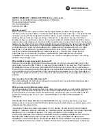
a.  Note how the rope is routed through the Rope 

Guide, around Lower Arm Pin, and into the Latch/
Strap Rope Pull Bracket. The new cable will be 
routed in the same manner. 

b.  Remove the current rope.

c.  Take the new Cable and Handle (Item B) and feed 

the Cable End Stop down through top Rope Guide, 
around the Lower Arm Pin, and slide down the 
inside of the Lower Arm. Looking through the hole 
in the underside of Lower Arm, use a Needle Nose 
Pliers or similar tool to grasp the Cable End Stop 
and pull it out through the hole a few inches. This 
will allow room to attach the Clevis. 

d.  Attach the Clevis (Item #8) to the Cable by sliding 

the clevis slot over the Cable and sliding the Cable 
End Stop into the Clevis. 

e.  Pull on the cable handle until the Clevis slides into 

the hole in the Lower Arm.

f.  Using a Needle Nose Pliers or similar tool insert the 

Clevis Pin and Retaining Ring (Item #10) through 
the slot in the side of the Lower Arm, into Clevis, 
through the hole in Latch/Strap Rope Pull Bracket 
and out the opposite side of the Clevis. Install 
Retaining Ring onto the groove of the Clevis Pin.

Cable 

End Stop

Cable 

End Stop

Needle 

Nose 

Pliers

Needle 

Nose 

Pliers

Cable

Lower 

Arm Pin

Lower 

Arm

Clevis

Clevis

Cable

Lower Arm 

Hole

Clevis 

Pin and 

Retaining 

Ring

B x 1

ITEM(S) NEEDED

#10 x 1

#8 x 1

Latch/Strap 

Rope Pull 

Bracket

Latch/Strap 

Rope Pull 

Bracket

1

2

A Johnson Outdoors Company

Minn Kota Consumer & Technical Service 
Johnson Outdoors Marine Electronics, Inc. 
PO Box 8129 
Mankato, MN  56001

121 Power Drive 
Mankato, MN 56001 
Phone (800) 227-6433 
Fax (800) 527-4464

minnkotamotors.com

©2019 Johnson Outdoors Marine Electronics, Inc.  

All rights reserved.  

Part #2374950

Rev D 

07/19

ECN 40103

ITEM(S) NEEDED

Summary of Contents for 1854125

Page 1: ...IP SOFT TOP 1 6 2280405 PULL GRIP SOFT BOTTOM 1 8 2370860 CLEVIS ROPE HANDLE 1 10 2372673 PIN CLEVIS 188 SS 1 a In order to remove the Bowguard Steering Module the Gas Spring needs to be disconnected...

Page 2: ...the other 3 Phillips screwdriver WARNING The gas assist lift mechanism in this unit is under high spring pressure when the motor is in the deployed position Do not remove the Steering Module assembly...

Page 3: ...emoved note how the rope is routed through the mount Rope Guide around the Pin and into Latch Strap Rope Pull Bracket The new cable will be routed in the same manner b Remove the current rope c Taking...

Page 4: ...the End Links on the mount Do this by positioning the Bowguard Steering Module above the End Links on the mount c Lower the Bowguard Steering Module straight down until seated End Links Keyways Clevi...

Page 5: ...dditional 3 Phillips screwdriver k Tighten screws until the heads are flush with the outer arm Phillips Screw Phillips Screw Phillips Screw Spacer Spacer Spacer Gas Spring Pin Gas Spring Cylinder Gas...

Page 6: ...nd Handle Item B and feed the Cable End Stop down through Rope Guide Eyelet and around the Lower Arm Pin d Attach the Clevis Item 8 onto the Cable by sliding the clevis slot over the Cable and sliding...

Page 7: ...levis e Pull on the cable handle until the Clevis slides into the hole in the Lower Arm f Using a Needle Nose Pliers or similar tool insert the Clevis Pin and Retaining Ring Item 10 through the slot i...

Page 8: ...lacez le moteur dans la position arrim e AVERTISSEMENT Les pi ces mobiles peuvent couper ou craser Le m canisme Lift Assist au gaz est sous pression Vous devez d connecter le ressort gaz avant de reti...

Page 9: ...s cruciforme n 3 AVERTISSEMENT Le m canisme Lift Assist au gaz dans l appareil est sous haute pression lorsque le moteur est en position d ploy e Ne retirez pas le module du gouvernail du support sans...

Page 10: ...rde dans le support le guide corde autour de la goupille et dans la ferrure du loquet de la sangle du c ble de traction Le nouveau c ble sera achemin de la m me fa on b Retirez la corde actuelle c Ave...

Page 11: ...tr mit sur le support Faites ceci en positionnant le prot ge proue module du gouvernail au dessus des liens d extr mit s sur le support c Abaissez le prot ge proue module du gouvernail tout droit jusq...

Page 12: ...t tes soient gales au bras externe Vis Cruciforme Vis Cruciforme Vis Cruciforme Entretoise Entretoise Entretoise Entretoise Goupille du Ressort Gaz Cylindre Ressort Gaz Cylindre Ressort Gaz Bras Exter...

Page 13: ...icle B acheminez la but e de fin du nouveau c ble dans l illet du guide corde et autour de la goupille du bras inf rieur d Fixez la manille article n 8 sur le c ble en glissant la fente de la manille...

Page 14: ...irez la poign e du c ble jusqu ce que la manille glisse dans le trou du bras inf rieur f l aide d une pince becs pointus ou un outil semblable ins rez la goupille de la manille et l anneau de retenue...

Reviews: