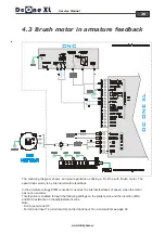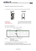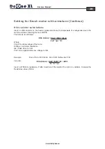
background image

13

Service Manual


 www.microphase.eu

Dc

DRIVE

CNC

DRIVE

CNC

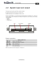
With a voltage (example from a CNC output) you can command the drive in torque mode.

Applying a signal of +/-10V at TPRC, the Drive to supply positive or negative peak current.
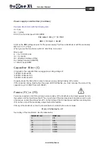
The formula to determine the value of Voltage to apply in TPRC in order to obtain requested current
is the following:

Example: (Drive size 10/20A,   request current 8A)

NOTE:
In current reference the loop of internal velocity automatically excludes itself .

Current output limitation

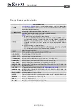
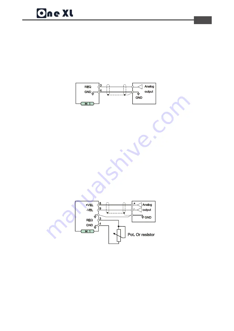
With an external potentiometer connected from GND and TPRC input, you have a limitation of output
current (from zero to max. size) drive's.

External potentiometer (470K-1M
Ohm) 3-10 TURNS

The speed loop remains active and uses the input reference /-VEL.
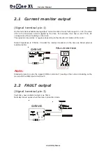
Connect between terminal and GND terminal REQ a resistor 1/4W or 1/8W. (The figure is used a
potentiometer). With external resistance tends to zero ohms, the output current tends to zero. Increasing
the ohmic value of resistance, the value of current supplied increases. With 47K of the current is
limited to 50% on the Maximum size. The loop motor speed remains active.

2.3

Current request (REQ)

V(TPRC) =  10 * Request current / PKcurrent Drive

V(TPRC) =  10 * 8 / 20 = 4V

(Signal terminal pin 3)

Summary of Contents for DC One XL

Page 1: ...Dc Service Manual Series Precision Servodrive for DC Motors MICROPHASE 36051 Creazzo Vicenza Italy Phone 39 0444 14 40 137 e mail info microphase eu DC One XL Precision Servo drive for DC Motors MICRO...

Page 2: ...iceable part Attempting to replace any internal component may result in damage to the unit and or personal injury This may also avoid the warranty Print in Italy rev 08 2017 DC BLDC SERVODRIVES Produc...

Page 3: ...coder inputs or tachogenerator input 16 2 8 Ausiliary power supply 5V 16 2 9 GND ground 16 Chapter 3 3 0 Power supply construction 17 18 3 1 Connections to earth and ground 19 3 2 Note about Connectio...

Page 4: ...e safety requirements may damage the equipment or injury the user This motion control equipment shoul be handled installed setted up and maintenanced only by competent personnel expert and trained in...

Page 5: ...motors where high dynamic performance and precise speed is required 1 2 Operation mode and feedback DESCRIPTION SPEED CONTROL INPUT It is speed piloting using an analogue reference differential or co...

Page 6: ...mA Power supply output 9 8V 9 8Vdc max 4mA Encoder max frequency 300Khz with level 2 8 24Vdc min max Fault drive output NPN 50mA max Start input Enable 9V 30Vdc min max Band width current 2KHz Band wi...

Page 7: ...witch 2 Adjustement zone 3 Calibration Potentiometers 4 Leds 5 Test point TEST Tacho test point 6 M1 Signal terminal 16 pins MC1 5 16 ST 3 81 pitch 3 81 7 M2 Power Terminals 5 pins GMST 2 5 5 G 7 62 p...

Page 8: ...zontally remove the cover The electrical box must have suitably filtered air vents Leave the necessary space both above and below the converters Keep the drive from excessive mechanical vibration 1 5...

Page 9: ...mensions in mm Supplementary ventilation V Standard radiator fan cooling below the converter operating temperature 0 to 45 C NO Mounting position YES If you need the converter mounted horizontally rem...

Page 10: ...signal of velocity speed The output from 0 to 8V is from zero to maximum speed At this point you can analyze the signal when you enable one of the following velocity feedback Encoder Armature Tachogen...

Page 11: ...ch corresponds to the drives peak current output In this mode the velocity loop is automatically disabled 4 GND Signal Common Ground Corrisponds to power supply s negative GND input 5 9 8V OUT Power s...

Page 12: ...irculating on the motor and the REQ input at terminal 3 Note On this terminal is available analog output current monitor of motor with range 0V 8V The value of 8V is the maximum current supplied by th...

Page 13: ...external potentiometer connected from GND and TPRC input you have a limitation of output current from zero to max size drive s External potentiometer 470K 1M Ohm 3 10 TURNS The speed loop remains act...

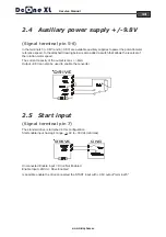
Page 14: ...t capacity of the output is max 4mA Output 9 8V can also be used to enable the converter 2 4 Ausiliary power supply 9 8V Is possible enable the drive connected the START input with 9 8V output termina...

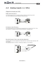
Page 15: ...lowing diagram shows an application using speed reference connections from C N C in the Common Mode This analog in common mode has a 20Kohm of impedance input Common mode reference The following figur...

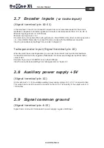
Page 16: ...en the motor have a tachogenerator you can use the terminal 10 as input for this feedback Connect this terminal to the negative of tachometer Do not exceed voltage as input from tacho value of 50V Exa...

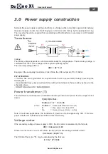
Page 17: ...an isolating rectified transformer secondary or a DC isolated power supply Voltage The primary voltage depends on what is available locally for a single phase The secondary voltage is calculated from...

Page 18: ...re unit E Ke n 1000 Vdc Im I motor A Ri Winding resistance Ohm Ke Voltage constant V kRPM n MAX speed RPM In regards to the capacitor filter we suggest a working voltage of 100VDC for Model 65 200VDC...

Page 19: ...ons 1 Connect to the ground bar the GND pin 4 of the Dc One the internal 0V zero voltage of the CNC the earth terminals of the PLC CNC frames the 0V of the auxiliary supply 2 Connect the ground bar to...

Page 20: ...lated power supply The conformity is assured only if it is installed following the precise assembly criteria expressed below The fundamental assembly characteristics are summarized below 1 The correct...

Page 21: ...r has been removed and the OK LED is off All of the personalizations are located inside of the DRIVE See figure above To gain access to the adjustment pads and the Dip switch unscrew and remove the co...

Page 22: ...r with the zero control signals of CNC To obtain good dynamic performance of the motor we recommend the use of encoders with at least 2000 2048PPR Acceptable performance is obtained anyway even with t...

Page 23: ...sistor calculations The resistor RENC determine what is the max speed of the motor at 10V of reference The result of RENC resistance is 20 or 22 Kohm Prefer resistance with 1 tolerance Once the resist...

Page 24: ...city is by tachogenerator feedback Signals from the encoder are connected only to the CNC for the control of space loop This function is enabled through the following settings on the solder point and...

Page 25: ...max voltage VEL reference express in Volts To calculate RDT resistor please use the following formula Once the resistor RDT is inserted proceed with final speed adjustment Operate using trimmer SPEED...

Page 26: ...armature feedback In the armature voltage PWM converter is used as the internal feedback of speed when the motor has not an encoder This function is enabled through the following settings on the sold...

Page 27: ...unter Clockwise Rotation the speed decreases The Range of regulation is about 25 Table Vdc voltage Value of RA in Kohm In this configuration the drive must set with the following Dip Switch and below...

Page 28: ...fter insertion of the resistor the motor is unstable increase the Resistance value of RCA Where Vmot Nominal voltage of the motor Ri Max cold motor resistance Ipk Peak drive current Vref max applied r...

Page 29: ...current will not be 14A but 10 5A Example on a converter 7 14A inserting a resistance RIN 6 8Kohm the rated output current will not be 7A but 5 7A RIP value 470 390 220 150 120 100 82 68 56 47 2 4 4...

Page 30: ...4 and 5 4 5 6 FUNCTION RANGE SETTING OFF OFF ON Ramp disabled NO SDT ON ON ON Ramp enabled 0 1 1sec Variable with ramp trimmer ON ON OFF Long ramp Insert RACC Variable with ramp trimmer RACC resistanc...

Page 31: ...to 1 Sec with 10 V input velocity SPEED Motor fine speed calibration With rotating clockwise CW or counterclockwise CCW is possible increase decrease the speed of the motor with range 25 OFFSET Offset...

Page 32: ...performed using a reference speed in VEL of about 1 or 2V You can use the voltage output from the CNC control paying attention to rule out the correction of space Or use an external oscillator or a s...

Page 33: ...rol when enabled Encoder signals incorrectly connected ENC A and ENC B signals swapped or encoder power supply missing or tachogenerator signals swapped OK OK IxT PTC OC IxT PTC O C FUNCTION OK GREEN...

Page 34: ...SW and L SW inputs See figure They may be used to block motor rotation when the machines overflow contact is intercepted Function At closing Limit swicth contact input to zero voltage you disable the...

Reviews: