23
Service Manual
www.microphase.eu
Dc
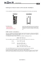
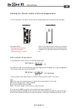
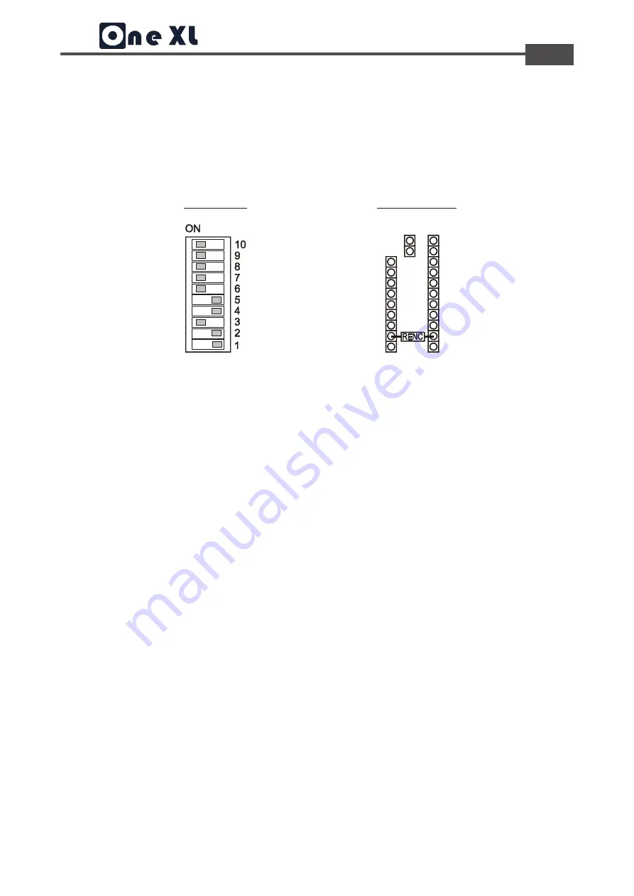
In this configuration, the drive must set with the following Dip Switch and below internal setting:
Dip Switch set for:
- Encoder feedback
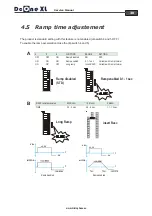
- Ramp time disabled
- Standard Dynamic constant
Setting for Brush motor with encoder feedback
Note: On the adjustement zone are not considered
here the other components used to determine other
calibrations "for example. Calibration current rating
etc.".
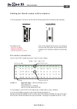
Example:
N° encoder (PPR) = 500
Motor max. speed 4000 rpm
Where:
RENC = 681*1000 / Fenc
Fenc = PPR * rpm / 60
Fenc = 500 * 4000 / 60= 33.333
RENC = 681*1000 / 33.333 = 20,4 kohm
RENC resistor calculations
The resistor RENC determine what is the max. speed of the motor at 10V of reference.
The result of RENC resistance is 20 or 22 Kohm. Prefer resistance with 1% tolerance.
Once the resistor RENC is inserted, proceed with final speed adjustment.
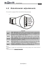
Operate using trimmer SPEED on the front of the drive. With Clockwise Rotation the speed increases.
With Counter Clockwise Rotation the speed decreases. The Range of regulation is about +/- 20%.
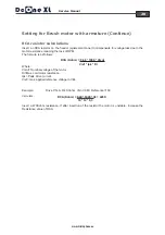
The drive is standard set with solder bridge S8 closed and the resistance calibration speed RENC
already mounted on board "27Kohm" (Calibration for speed = 3000rpm encoder with 10V reference
and 500PPR line-count resolution encoder.)
For change this resistance open the drive and calculation the following formula:
DIP SWITCH
ADJUSTEMENT

