Micrel Confidential
9
June 2006
2180 Fortune Drive, San Jose, CA 95131, USA
•
(408) 944-0800
•
http://www.micrel.com
KSZ8862-16 MQL Demo Board User’s Manual
5.2
Demo Board Block Diagram
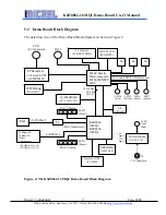
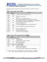
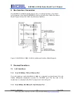
The detail top view of the Demo Board block diagram is shown in Figure 4.
Figure 4: The KSZ8862-16 MQL Demo Board Block Diagram
M16C Family
Microcomputer
M30626FHPFP
MCU
KSZ8861-
16MQL
KSZ8862-
16MQL
EEPROM
(AT93C46)
Crystal or OSC
(25 MHz)
16-Bit SRAM
(CY7C1021CV33)
Power Supply
(
U8/U9/U10
)
S4
(Reset)
S1
RJ45
100Base-SX
10Base-FL
Fiber
Components
T2
S2
S3
RS 232 (P1)
(MAX232)
2 x Crystals
(32 KHz/12 MHz)
8 Characters
x 2 Lines LCD
(
ACM0802B)
ICD Debug
Port (J2)
LAN-Port 2
(Pulse Transformer)
Port 1 Status
Port 2 Status
LED1
(Green)
LED2
(Green)
POT2
POT1
(LCD Contrast)
(S 1-3 and LED 4-7 for Demo use)
LED7
(Green)
LED6
(Green)
LED5
(Yellow)
LED4
(Red)
+3.3V
J3
+7.5V Input Jack
LED3
Power
(Red)
16-Bit Bus
D[15:0]
A[15:0]
LAN-Port 1
+5V
(RX HFBR-2416, U4)
(TX HFBR-1414, U3)

