Micrel Confidential
17
June 2006
2180 Fortune Drive, San Jose, CA 95131, USA
•
(408) 944-0800
•
http://www.micrel.com
KSZ8862-16 MQL Demo Board User’s Manual
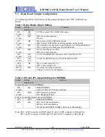
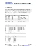
9 D1_SUP
Reserved.
8-6 Reserved
Reserved.
5 DSI
Reserved.
4 Reserved
Reserved.
3 Reserved
Reserved.
2 Reserved
Reserved
1
Clock_Rate
Internal clock rate selection (Note 1)
0: 125 MHz
1: 25 MHz
0 ASYN_8bit
Async 8-bit or 16-bit bus selection
1= Async bus is configured for 16-bit width
0= Async bus is configured for 8-bit width
(32-bit bus, KSZ8862-32MQL, don’t care this bit
setting)
Note 1: At power up, the Ethernet chip operates from the 125 MHz clock. The internal frequency can
be dropped to 25 MHz via the external EEPROM.
7.2
Board Reset
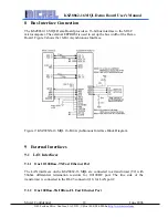
The KSZ8862-16 MQL Demo Board generates a reset signal from the reset circuitry
during power up. It also provides a push button S4 reset circuit to reset the whole Demo
Board. At power up, the board is automatically reset. User can also press reset button S4
on the board for a manual reset. After any reset, the LED1 and LED2 flash to indicate the
power on self-test, also the LCD module shows the HW/SW board status and system set
up result.
7.3
Clock Scheme
The Ethernet chip reference clock is provided from external 25 MHz crystal (Y1). The
crystal is connected to the X1 and X2 pins on the KSZ8862-16 MQL. This 25 MHz clock
is specified as +3.3V tolerant, +/- 50 ppm. If an oscillator is used, X1 connects to a 3.3V
tolerant oscillator and X2 is no connection.
The M16C microcomputer receives two references clocks, one is the 12 MHz crystal,
connected to Xout/Xin pins, the other is the 32 KHz crystal, connected to XCout/XCin
pins. Both clocks are specified as +5.0V tolerant, +/- 100 ppm.
7.4
POT1 and POT2
Adjust POT1 to change the contrast of the LCD display module.
Adjust POT2 to change the UDP receive value when streaming from Demo Board to PC
on the demo software.

