Micrel Confidential
11
June 2006
2180 Fortune Drive, San Jose, CA 95131, USA
•
(408) 944-0800
•
http://www.micrel.com
KSZ8862-16 MQL Demo Board User’s Manual
5.4
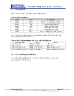
LED Definition
Table 3 shows the 10FL_100SX Demo Board LED definition.
Table 3: LEDs Definition
LED
Color
Description
LED1
Green
Group of 4-LED for Port 1 Status
LED2
Green
Group of 4-LED for Port 2 Status
LED3
Red
+5V Power LED indicator
LED4
Red
For HW/SW demo LED
LED5
Yellow
For HW/SW demo LED
LED6
Green
For HW/SW demo LED
LED7
Green
Received WOL packet LED indicator
Port 1 and 2 status LED indicators are programmable via the register to three different
modes, as described in Table 4 below.
Table 4:Three Different Modes for Port 1 and 2 LED Status
Mode 0 (Default)
Mode 1
Mode 2
LED3= No define
LED3= No define
LED3= Act
LED2= Link/Act
LED2= 100 Link/Act
LED2= Link
LED1= Full duplex/Col
LED1= 10 Link/Act
LED1= Full duplex/Col
LED0= Speed (on 100/off 10) LED0= Full duplex
LED0= Speed (on 100/off 10)
5.5
LCD (Liquid Crystal Display)
The LCD Module (ACM0802B) is a 2-line by 8-character display to use for demo
received packet or HW/SW status.

