background image


Micrel Confidential 

16 

June 2006 

2180 Fortune Drive, San Jose, CA 95131, USA 

 (408) 944-0800 


http://www.micrel.com


KSZ8862-16 MQL Demo Board User’s Manual


7


Hardware Description 


7.1


Memory Map 

 
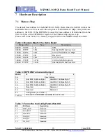
The default base address for the KSZ8862-16 MQL Demo Board is 0x0300 without the 
EEPROM. Due to CS2 is used for the chip select of KSZ8862-16 MQL, the system base 
address is 0x10300. If the EEPROM is used, the base address will download from the 
first two bytes of the EEPROM to register of the Ethernet chip on power up. 
Please refer to the Table 5 for memory map and Table 6 for EEPROM format/content. 
 

Table 5: Memory Map for the Demo Board  

Range (16) 

Size 

Description 

00000 – 003FF 

1K 

SFR 

00400 – 09FFF 

39K 

Internal RAM and reserved 

10000 – 26FFF 

94K 

CS2 for KSZ8862-16 MQL 

27000 – 27FFF 

4K 

Reserved 

28000 – 2EFFF 

28K 

CS1 (No use) 

30000 – 7FFFF 

327K 

CS0 for SRAM (option) 

80000 - FFFFF 

524K 

Internal RAM and reserved 


Table 6: EEPROM Format and Content 

WORD 

15                                             8 

7                                                   0 

0H Base 

Address 

1H 

Host MAC Address Byte 2 

Host MAC Address Byte 1 

2H 

Host MAC Address Byte 4 

Host MAC Address Byte 3 

3H 

Host MAC Address Byte 6 

Host MAC Address Byte 5 

4H 

Reserved Reserved 

5H 

Reserved Reserved 

6H 

ConfigParam (see Table 7) 

7H-3FH 

Not used for KSZ8862M (available for user to use) 


Table 7: Format for the ConfigParam Word 6H 

Bit Bit 

Name 

Description 

15  

NEW_CAP 

Reserved. 

14 NO_SRST 

Reserved. 

13 Reserved 

Reserved. 

12 PME_D2 

Reserved. 

11 PME_D1 

Reserved.


10 D2_SUP 

Reserved. 

Summary of Contents for 10/100BT

Page 1: ...ial 1 June 2006 2180 Fortune Drive San Jose CA 95131 USA 408 944 0800 http www micrel com KSZ8862 16 MQL Demo Board User s Manual KSZ8862 16 MQL 10FL_100SX and 10 100BT Demo Board User s Manual Versio...

Page 2: ...ARD BLOCK DIAGRAM 9 5 3 DEMO BOARD JUMPER CONFIGURATION 10 5 4 LED DEFINITION 11 5 5 LCD LIQUID CRYSTAL DISPLAY 11 6 GETTING START FOR DEMONSTRATION 12 6 1 POWER ON THE DEMO BOARD 12 6 2 SET UP IP ADD...

Page 3: ...rd 12 Figure 6 Set Up the PC for IP Address 13 Figure 7 Input IP Address and Establish Connection for TCP UDP Demo 14 Figure 8 Receive and Transmit TCP UDP Packets for Demonstration 15 Figure 9 KSZ88X...

Page 4: ...utility to allow quick and easy device setup 2 Hardware Features KSZ8861 16 MQL demo board supports the single either fiber or copper port Ethernet MAC controller and 16 bit bus interface to M16C micr...

Page 5: ...DC Power Supply RTA FoUSB MON In Circuit Debugger sold separately Mini USB Cable sold separately Target Cable sold separately Software Tools FoUSB Programmer and other development tools Note RTA FoUSB...

Page 6: ...B MON Micrel has programmed the OpenTCP device driver into the Demo Board for demonstration purposes so the user can use the Demo Board to run demo software TCP_GUI or LinkMD on the Demo Board If you...

Page 7: ...n A serial female to male cable is used in the demo kit The cable is connected between the RS 232 port of the PC and the serial port of the Demo Board From the console port in the PC the user can read...

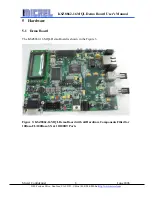
Page 8: ...USA 408 944 0800 http www micrel com KSZ8862 16 MQL Demo Board User s Manual 5 Hardware 5 1 Demo Board The KSZ8862 16 MQL Demo Board is shown in the Figure 3 Figure 3 KSZ8862 16 MQL Demo Board with al...

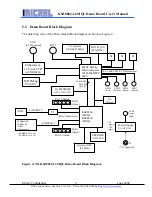
Page 9: ...6MQL KSZ8862 16MQL EEPROM AT93C46 Crystal or OSC 25 MHz 16 Bit SRAM CY7C1021CV33 Power Supply U8 U9 U10 S4 Reset S1 RJ45 100Base SX 10Base FL Fiber Components T2 S2 S3 RS 232 P1 MAX232 2 x Crystals 32...

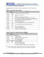
Page 10: ...ll chip power down OFF for normal operation JP8 8 pin CS2 5 6 5 6 ON for KSZ8862M chip select CS2 from M16C CPU JP9 8 pin CS0 1 2 1 2 ON for SRAM chip select CS0 from M16C CPU JP10 2 pin ON ON to conn...

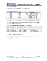
Page 11: ...emo LED LED6 Green For HW SW demo LED LED7 Green Received WOL packet LED indicator Port 1 and 2 status LED indicators are programmable via the register to three different modes as described in Table 4...

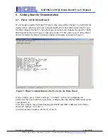
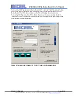
Page 12: ...PC open the Hyper Terminal and configure the speed to 38400 Bits Second as shown in Figure 2 then plug in the 7 5V DC jack to power on the Demo Board Normally the Hyper Terminal window will display as...

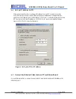
Page 13: ...UI demo software and the demonstration for KSZ8862 16 MQL Ethernet chip Due to the default value of IP address is 192 168 1 1 in the Demo Board For the PC the user can set the IP address to 192 168 1...

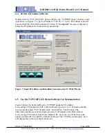
Page 14: ...onnection is successfully Figure 7 Input IP Address and Establish Connection for TCP UDP Demo 6 5 Use the TCP UDP GUI Demo Software for Demonstration Figure 8 shows the Send and Receive TCP UDP packet...

Page 15: ...ng button in the UDP Receive Routine area then adjust POT2 10K variable resistor on the Demo Board The GUI demo window on the PC will display the current value For sending UDP packets from PC to Demo...

Page 16: ...for the Demo Board Range 16 Size Description 00000 003FF 1K SFR 00400 09FFF 39K Internal RAM and reserved 10000 26FFF 94K CS2 for KSZ8862 16 MQL 27000 27FFF 4K Reserved 28000 2EFFF 28K CS1 No use 3000...

Page 17: ...circuit to reset the whole Demo Board At power up the board is automatically reset User can also press reset button S4 on the board for a manual reset After any reset the LED1 and LED2 flash to indica...

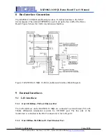
Page 18: ...bus width of the Demo Board Figure 9 shows the 16 Bit Asynchronous Interface Figure 9 KSZ88XX 16 MQL 16 Bit Asynchronous Interface Block Diagram 9 External Interfaces 9 1 LAN Interfaces 9 1 1 One 10 1...

Page 19: ...an UART serial interface P1 for serial data communication between hyper terminal and Demo Board 9 3 ICD In Circuit Debugger This In Circuit Debugger interface J2 is used for USB debugger and FoUSB pr...

Reviews: