Micrel Confidential
19
June 2006
2180 Fortune Drive, San Jose, CA 95131, USA
•
(408) 944-0800
•
http://www.micrel.com
KSZ8862-16 MQL Demo Board User’s Manual
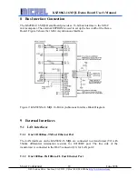
With the additional circuitry, the LAN port 1 interface can support 100Base-SX/10Base-
FL with fiber optic components (U3/U4). The 100Base-SX/10Base-FL fiber optic mode
is supported by KSZ8862-16 MQL only.
The HFBR-1414 (U3) high power transmitter and HFBR-2416 (U4) 125 MHz receiver
pair up to provide a duplex solution optimized for 100Base-SX/10Base-FL fiber optic
components.
9.2
UART
The KSZ8862-16 MQL Demo Board provides an UART serial interface (P1) for serial
data communication between hyper terminal and Demo Board.
9.3
ICD (In-Circuit Debugger)
This In-Circuit Debugger interface (J2) is used for USB debugger and FoUSB
programmer downloading.
9.4
Power Jack
A +7.5V DC input is connected to the power jack J3 to supply the Demo Board.
9.5
Power Supply and Test Point
The Demo Board is supplied with +7.5V DC power through a jack (J3) and converted to
+3.3V with a 3.3V voltage regulator (U9, MIC29302BT). The KSZ8862-16
MQL contains an in1.2V LDO, to provide its core, analog and PLL voltages.
The Table 8 shows all test points information.
Table 8: All Test Points Description
Test Points
Comment
TP1
Power supply for 1.2V Analog VDDA
TP2
LDEVN (pin17) signal from KSZ8862-16
MQL output

