Micrel Confidential
10
June 2006
2180 Fortune Drive, San Jose, CA 95131, USA
•
(408) 944-0800
•
http://www.micrel.com
KSZ8862-16 MQL Demo Board User’s Manual
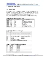
5.3
Demo Board Jumper Configuration
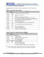
The following Tables 1 and 2 show all the jumper settings for the 10FL_100SX Demo
Board.
Table 1: Demo Board Jumper Setting
Jumper
Setting
KSZ8862M
Comment
JP1
(3-pin)
ON
(1-2)
1-2 ON to select 10FL_100SX fiber mode.
JP2
(2-pin)
OFF
OFF: for normal operation
ON: NA
JP3
(2-pin)
ON
ON: to select 10FL_100SX fiber mode
OFF: to select 100FX fiber mode (not supports on this board)
JP6
(2-pin)
OFF
ON: with power management to use Wake up on LAN for KSZ8861M
OFF: without power management for KSZ8862M
JP7
(2-pin)
OFF
ON: for full-chip power down
OFF: for normal operation
JP8
(8-pin)
CS2
(5-6)
5-6 ON for KSZ8862M chip select (CS2) from M16C CPU
JP9
(8-pin)
CS0
(1-2)
1-2 ON for SRAM chip select (CS0) from M16C CPU
JP10
(2-pin)
ON
ON: to connect internal 3.3V
OFF: to use external 3.3V
JP11/12
(3-pin)
OFF
No connect for normal operation
Connect 1-2 or 2-3 for test purpose
Table 2: JP4 and JP5 Jumper Settings for EEPROM
Jumper
Setting
KSZ8862M
Comment
Normal Operation with EEPROM
JP4
(2-pin)
ON
With EEPROM
(refer to Table 6/7 for bus selection)
JP5
(2-pin)
OFF
OFF: Normal operation
ON: Illegal operation
8-bit or 16-bit Operation without EEPROM
JP4 OFF
Without
EEPROM
JP5
ON
ON: for 16-bit bus interface
Off: for 8-bit bus interface
(32-bit bus, KSZ8862-32MQL, don’t care this setting)
Note: Pin 1 of JP4 connects to EEEN (pin 26); pin 2 of JP4 connects to 10K pull up.
Pin 1 of JP5 connects to EEDI (pin 30); pin2 of JP5 connects to 10K pull up.

