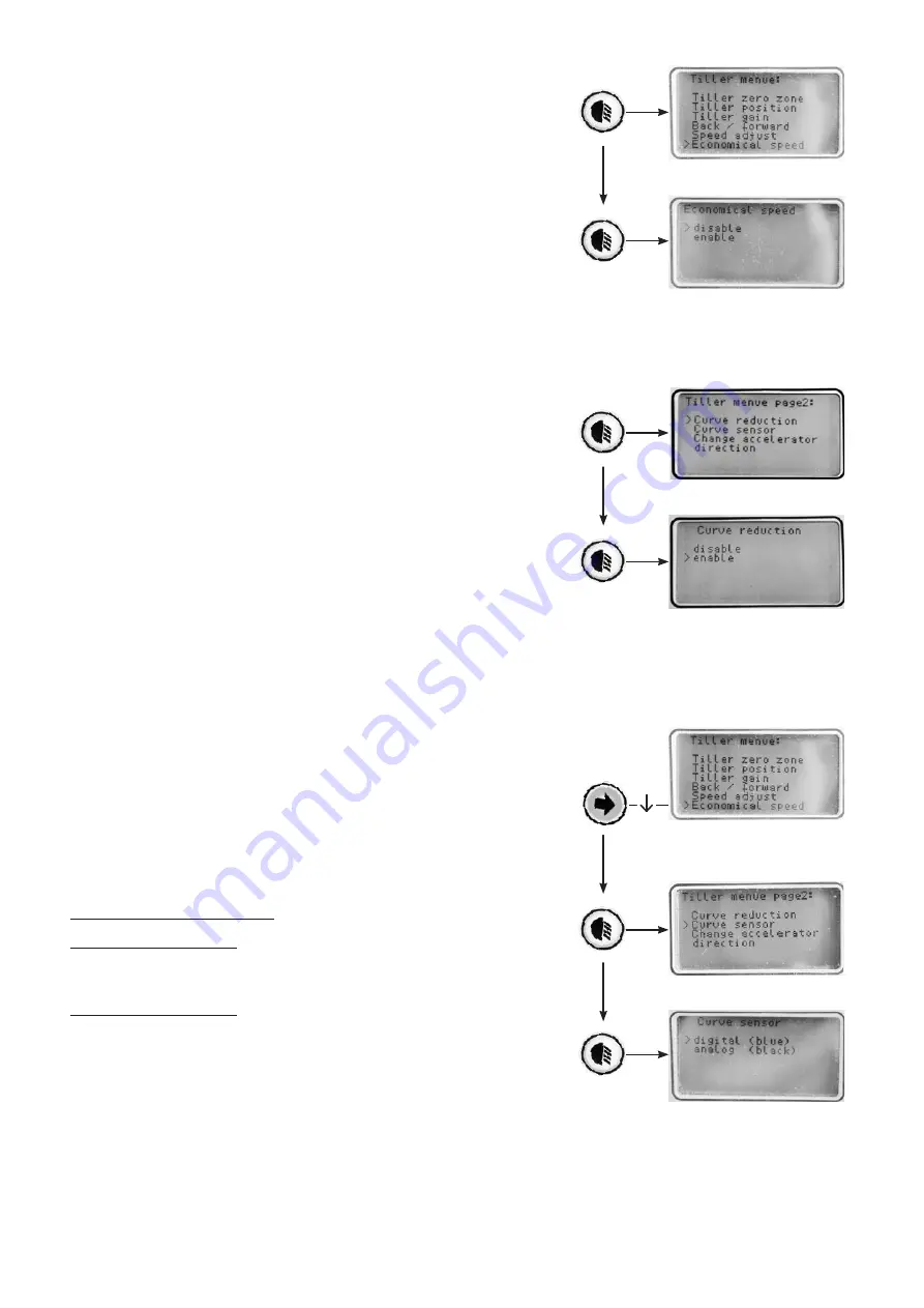
Meyra 1.163 Service Manual Download Page 68

68

Economical speed

Here you can activate or deactivate the cruise con-
trol.

Curve reduction

Here you can activate or deactivate the speed re-
duction in curves.

 While driving in curves the speed is reduced to 

about 7.5 km/h.

 When  the  final  speed  is  set  to  6 km/h  a  curve 

speed setting is not possible.

Curve sensor

This  setting  adjusts  the  existing  curve  sensor.  The 
curve sensor is located behind the headlight.

 With an incorrect selection of the curve sensor 

this function is not or incorrectly processed.

Curve sensor digital (blue) for Cityliner:
Model 3.263 / 3.264 and
Model 2.663 / 2.664

Curve sensor analogue (black) for Ortocar:
Model 2.563 / 2.564

Summary of Contents for 1.163

Page 1: ...GB SERVICE MANUAL SCOOTER Models 1 163 3 264 1 363 1 364 2 363 2 364 2 663 2 664 2 563 2 564 1 W e m o v e p e o p l e...

Page 2: ...2...

Page 3: ...Drive 13 Replacing the drive Cityliner 13 Separating electric connections 14 Disassembly of the drive 16 Assembly of the drive unit 19 Replacing the drive Ortocar SP II 21 Disassembly of the drive 22...

Page 4: ...ing lever complete 49 Exchanging the director foot pedal complete 50 Exchanging the director hand gas complete 51 Power electronic 52 Parametrics 53 Programming sequence 54 Programming unit SP1 55 Pur...

Page 5: ...es 70 Battery replacement on model 1 163 70 Battery replacement on other models 70 Maintenance 71 Maintenance checklist 72 Electrical system 72 Mechanic 74 DIN norms and guidelines 75 Error code displ...

Page 6: ...l documents can also be downloaded from the following site in the internet www meyra ortopedia de Requirements Special knowledge is required to carry out the maintenance work described in this service...

Page 7: ...ial number beside the space SN On older vehicles it is the vehicle identi cation number underneath the space Fz I Nr Term de nitions Here you will nd explanations to the term used in this manual Servi...

Page 8: ...8 OVERVIEW Cityliner 306 model 1 163 Cityliner 408 model 3 264 Cityliner 406 model 3 264...

Page 9: ...9 Cityliner 310 model 1 363 Cityliner 410 model 1 364...

Page 10: ...10 Cityliner 312 model 2 363 Cityliner 412 model 2 364...

Page 11: ...11 Cityliner 315 model 2 663 Cityliner 415 model 2 664...

Page 12: ...12 Ortocar 315 SP II model 2 563 Ortocar 415 SP II model 2 564...

Page 13: ...ving or does not bring any performance without an error being indicated the carbon brushes and the collector in the motor 2 have to be checked Worn carbon brushes with dull contacts are to be replaced...

Page 14: ...If necessary remove the electronic cover 1 2 Unplug the cable connections of the motor and spring pressure brake if required drive locking lever only in respect to the S Drive electronic from the con...

Page 15: ...Unscrew the countersunk screws 1 and care fully lift of the rear cover 2 2 Pull the cable shoes 3 of the battery cable 3 Disconnect the plugged connection 4 of the motor cable For this activate the r...

Page 16: ...64 and Model 2 363 2 364 1 Disconnect the joint connection 1 of the hand ventilated pressure brake magnetic brake Model 1 363 1 364 Model 2 363 2 364 and Model 2 663 2 664 2 Dismantle the two screwed...

Page 17: ...7 7 6 6 5 17 Model 3 264 Model 1 363 1 364 and Model 2 363 2 364 3 Dismantle the two screwed connections 5 of the attachment clamp on both sides of the drive 6 4 Lift the drive out of the frame 7...

Page 18: ...uard 4 Dismantle the two screwed connections 5 of the attachment clamp on both sides of the drive 5 Lift the drive out of the frame Only on model 2 663 2 664 4 Dismantle the two screwed connections 7...

Page 19: ...ght Note Watch for the correct assembly position of the drive 3 Mount the attachment clamps of the drive to the rear frame 4 Mount the joint connection of the hand venti lated pressure brake magnetic...

Page 20: ...spring pressure brake respectively drive locking lever 12 only with respect to the S Drive electronic 7 If neccessary replace the electronic cover and mount it 9 8 If neccessary fasten the motor cabl...

Page 21: ...e drive the rear chassis has to be detached 1 Therefore observe the corresponding chapter of the respective user manual 2 Afterwards disassemble the drive wheels 3 For further assembly work it is reco...

Page 22: ...shock absorbers 2 For this you need to slightly compress the spring of each shock absorber Afterwards disassemble the lower screw 3 of the two shock absorbers or without mounting jig 1 First disassem...

Page 23: ...Dismantle the attachment screws 1 2 on both sides and remove the rocker 3 4 Now disconnect the following electric connec tions of the drive Motor plug 4 Brake plug 5 Microswitch plug 6 5 Lift the dri...

Page 24: ...1 on both sides of the drive and mount then to the rear with attachment screws 2 3 4 The side parts must be dirt and grease free 6 near the gliding washers 5 2 Now connect the following electric conn...

Page 25: ...3 1 1 2 25 3 Insert the shock absorber and assemble the two screwed connections 1 For this you need to slightly compress the spring of each shock absorber 4 Mount the wheel ange 2 on both sides 3...

Page 26: ...cle Testing the electric functions Switch the scooter on and check all functions Switch to push mode and check the exibility of the scooter The vehicle may no longer drive when it is switched on Testi...

Page 27: ...tor brake With the programmable delay the braking process can be adjusted from soft to full stop Magnetic brake The magnetic brake 1 is anged to the motor 2 It serves as a parking brake and if the mot...

Page 28: ...w spring pressure brake magnetic brake the cables are to be reconnect ed Model 1 163 Unscrew the attachment screws 1 and remove the spring pressure brake Model 3 264 Model 1 363 1 364 Model 2 363 2 36...

Page 29: ...screw the attachment screws 2 and remove the cover cap brake Unscrew the attachment screws 3 and remove the spring pressure brake Assembly The assembly is done analogue in reverse order An adjustment...

Page 30: ...p to 3 mm length They are also to be replaced when the contacts appear black and dull On intact carbon brush es the contacts are anthracite coloured and shin ing Disassembly of the carbon brushes Mode...

Page 31: ...after in spection watch for their position and place ment They have to be replaced in the same position in the same direction not turned by 180 Assembly The assembly is done analogue in reverse order...

Page 32: ...is to be replaced Inspection of the collector Remove one carbon brush for inspection 7 View chapter Disassembly of the carbon brush es Note With a special torch with endoscopic tube 8 you can additio...

Page 33: ...ignment is correct when the rear rim horns are 2mm further apart than the front ones 2 mm toe in Note As a replacement for the wheel alignment meas ure you can also use two boards of about 30 cm lengt...

Page 34: ...3 2 364 2 Loosen the counter nut 1 of the front tie rod 3 Turn the tie rod until the correct toe in of the right hand steering wheel is achieved view chapter checking the alignment 4 Retighten the cou...

Page 35: ...tiller revetment 1 Unscrew the attachment screws 1 of the rear steering tiller revetment 2 Remove the rear tiller revetment Removing the front tiller revetment 1 Unscrew the basket holder 2 Unscrew th...

Page 36: ...the front tiller revetment 1 Unscrew the basket holder 1 2 Unscrew the operating panel Therefor remove the three attachment screws 2 3 Carefully lift off the operating panel 3 4 Unscrew the attachmen...

Page 37: ...2 Unscrew 3 or pull off 4 the release lever 3 Loosen the four clamping screws 5 Afterwards unhook the rear tiller revetment and pull it off Model 2 563 2 564 Unhook the rear tiller revetment on both...

Page 38: ...bow den cable 4 Unhook the bowden cable at the brake shield 5 and pull it upward out of the rubber buffer 8 Pre assembly of the bowden cable 1 Insert the bowden cable into the hand brake le ver 3 Mode...

Page 39: ...iller Afterwards align the two bowden cables under neath the Y plug 1 left and right and through the sleeve 2 3 Fasten the upper bowden cable with a cable binder The upper bowden cable must lie freely...

Page 40: ...king the teeth must grip tightly into each other Model 1 363 1 364 Loosening the tiller lock is achieved through the lever 2 that turns the blocking spring with a bow den cable The locking device for...

Page 41: ...p 1 or re tracting grip 2 that releases the blockage of the gas spring The locking device for the tiller may when activating the lever 1 resp 2 only disengage after about 5 mm lever way 1 Loosen the c...

Page 42: ...l bulb is defective the remaining one blinks at double frequency A brake light is serially included in all vehicles with lighting features It is activated for a short period when the director is relea...

Page 43: ...ff with the driving key Model 1 163 Model 3 264 and Model 1 363 1 364 Malfunctions are displayed through the blinking status display 1 Model 2 363 2 364 Model 2 663 2 664 and Model 2 563 2 564 Error m...

Page 44: ...ly behind the keypad Therefore observe chapter Operating panel PCB 1 Operating keypad PCB 2 Additional PCB to the control panel PCB does not apply for the S Drive electronic Director Fundamental job o...

Page 45: ...the operat ing panel 1 Note Carefully lift the operating panel and swivel it to the side 2 Take out the operating panel PCB 3 Pull the plug from the defective PCB and attach it to the new operating p...

Page 46: ...e operating panel Note Carefully lift the operating panel and swivel it to the side 2 3 Pull the plug from the operating panel PCB 4 Remove the screws 4 of the additional PCB and remove it 5 Unscrew t...

Page 47: ...anel housing and swivel it to the side 2 2 Pull the plug from the operating panel PCB Assembly of the operating keypad PCB Assembly of the operating panel is done analogue in reverse order Note The op...

Page 48: ...ormer Disassemble the four screws 1 of the voltage transformer 2 Note Carefully lift the voltage transformer and swivel it to the side Pull the plug 3 from the PCB of the voltage transformer Assembly...

Page 49: ...n A Model 1 163 up to October 2008 also Model 3 264 and Model 1 363 1 364 Model dependent version A B Model 2 363 2 364 Model 2 663 2 664 and Model 2 563 2 564 from October 2008 addtl Model 3 264 and...

Page 50: ...the speed Level 0 0 V to 0 5 V are directed to the power electronics in the rear Model dependent version A B Model 2 363 2 364 Model 2 663 2 664 and Model 2 563 2 564 Exchanging the director foot ped...

Page 51: ...cted to the power electronics in the rear Model dependent version B Model 2 363 2 364 Model 2 663 2 664 and Model 2 563 2 564 Exchanging the director hand gas complete 1 Pull the plug 2 on the operati...

Page 52: ...the operating panel The drive performance is initialised through a proc essor controlled power ampli er The operating data dynamic properties and limit values of the driving behaviour is stored in the...

Page 53: ...the following parts depending on the power electronic SOLO electronic Hand programming unit SP1 1 Item No 208 111 200 Device no D 49371 PC program adapter cable 3 Item No 208 112 700 Device no D 50380...

Page 54: ...ooter on Note The programming device is automatically switched on together with the vehicle 4 Conduct the programming View chapter Programming unit SP1 or chap ter PC programming 5 After programming p...

Page 55: ...the help key pressed down a running text appears in the display It describes the function of the selected parameter view driving pa rameters Yes or up key Upward movement within the parameter menu res...

Page 56: ...100 manufacturer ma ximum 5 Forward Speed Maximum forward speed ad justable from 0 or manufacturer minimum to 100 manufacturer maximum 6 Reverse Speed Maximum backward speed adjustable from 0 or manu...

Page 57: ...driving parameter is shown in the display Changing the value of the driving param eter Adjust the driving parameter to the desired value by pressing the up or down key By pressing the Enter key the a...

Page 58: ...the Enter key Increase the setting for fast to 50 by repeatedly pressing the up key Con rm the setting for fast with Enter Also increase the setting for slow to 50 by re peatedly pressing the up key...

Page 59: ...al limits of the user and the main eld of operation must be considered For operating the vehicle in cramped surroundings it is not reasonable for ex ample to adjust the acceleration and the speed to a...

Page 60: ...t need to make some adjustments of the driving behaviour according to the disease pattern For notes hereto view Tips for the adjustment Programming sequence First view chapter Programming sequence Con...

Page 61: ...ce menu 1 Switch off the vehicle 2 Keep the keys right and left turn signal depressed and 3 switch the vehicle back on 4 Keep the keys depressed until the service menu appears The menu text is shown i...

Page 62: ...s stored At the same time you switch back into the previous menu Abort leave menu By pressing the reverse driving direction key the process is aborted and the previous menu appears If a selection has...

Page 63: ...switch from summer to winter time The LCD display shows the adjusted time Hours With each pressing of the speed control key the clock in the Time menu is advanced by one hour Minutes With each pressin...

Page 64: ...and hand gas must be selected manually After selection of the vehicle type switch through the menu Lighting to submenu Final speed Here you can set the max nal speed of the ve hicle After selection o...

Page 65: ...ow Audible warning The pulsed horn can be switched on or off A pulsed horn signal sounds depending on pro gramming while the indicators are active or while driving backwards The following parameters c...

Page 66: ...e of the set gure The value of 7 in the zero zone from 7 to 7 is set by the manufacturer The zero zone can be set larger but not less than 7 If the value of the director is larger than the set value a...

Page 67: ...backward key activated disable accelerator lever Rotary handle Foot accelerator Wig Wag throttle Driving lever in combina tion with the reverse key From software version V1 42 foot pedal gas and driv...

Page 68: ...m h When the nal speed is set to 6 km h a curve speed setting is not possible Curve sensor This setting adjusts the existing curve sensor The curve sensor is located behind the headlight With an incor...

Page 69: ...re backlit in correspondence with the parameters when the lights are switched on The backlight can be switched on or off The following parameters can be selected in the backlight menu 1 2 Backlight of...

Page 70: ...e cables carefully lift and swivel the battery pack cover to the side 2 2 Pull the cable shoes from the battery poles 3 Remove the glued sensors 4 from the batter ies Do not pull on the cables 4 Remov...

Page 71: ...maintenance the itemised maintenance checklist can be used The maintenance checklist is designed for duplication through copying The lled in maintenance checklists are to be added to the documentation...

Page 72: ...the cable layout Plugged connectors undamaged and not corroded Are the holders for the charging and controller fuse a well as the main fuse lled cor rectly Are the cables to the lighting units and sen...

Page 73: ...ion of the set speed Working angle of the reduction automatic identical left and right Braking behaviour Stopping distance is met after the driving encoder is released at maximum speed with the max pe...

Page 74: ...able Handle bar The steering column does not show slackness in any direction Does the steering column locking device work awlessly Handgrips are undamaged and t tightly Frame Locking device between fr...

Page 75: ...than 1 5 mm Tyres free of damages or foreign bodies and not brittle Pressure front and rear Hubs do not show tears or raptures Hubs without axial run out of more than 2 mm Wheel attachment screws tig...

Page 76: ...lace charging socket E07 Director error Director error between operating panel and the Solo electronic check cable replace Solo electronic E08 Controller error Solo S Drive Replace Solo S Drive electr...

Page 77: ...on check cables E14 not used E15 not used E16 not used E17 ROM error Internal error in the operating panel replace operating panel E18 Watchdog error Internal error in the operating panel replace oper...

Page 78: ...78 NOTES...

Page 79: ...79 NOTES...

Page 80: ...schaft mbH Meyra Ring 2 D 32689 Kalletal Kalldorf P O Box 1 703 D 32591 Vlotho Fon 49 0 5733 922 366 Fax 49 0 5733 922 9366 info meyra ortopedia de www meyra ortopedia de W e m o v e p e o p l e 205 3...

Reviews: