4B - 4 - IGNITION SYSTEM
90-816462 2-695
Precautions
!
WARNING
When performing the following procedure, be
sure to observe the following:
•
Be sure that engine compartment is well ven-
tilated and that no gasoline vapors are pres-
ent, to avoid the possibility of fire.
•
Be sure to keep hands, feet and clothing clear
of moving parts.
•
Do not touch or disconnect any ignition sys-
tem parts while engine is running.
•
Do not reverse battery cable connections.
System is negative (–) ground.
•
Do not disconnect battery cables while en-
gine is running.
Spark Plugs
1. Inspect each plug individually for badly worn elec-
trodes, glazed, broken or blistered porcelain and
replace plug where necessary.
2. Inspect each spark plug for make and heat range.
All plugs must be the same make and number or
heat range. Refer to “Specifications” for spark
plug numbers.
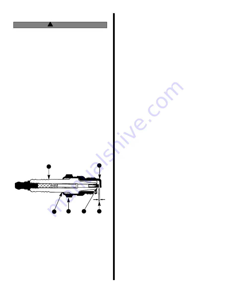
3. Adjust spark plug gaps with a round feeler gauge.
50674
b
a
e
c
d
f
Spark Plug Detail
a - Porcelain Insulator
b - Check For Cracks In This Area of Porcelain
c - Shell
d - Proper Gap
e - Side Electrode (Bend to Adjust Gap)
f - Center Electrode (File Flat When Adjusting Gap) - Do Not .
Bend
IMPORTANT: Tapered seat spark plugs are not in-
terchangeable with non-tapered (with gasket)
spark plugs.
4. Clean spark plug seating area. DO NOT use gas-
kets on taper seat plugs. Install spark plugs and
torque to 15 lb. ft. (20 N·m.). Heat transfer and a
gas-tight seal must be achieved.
Spark Plug Wires
1. Inspect spark plug wires for damage.
2. Check spark plug wires for continuity.
3. Replace any wires that are cracked, cut, or have
damaged spark plug boots.
4. Replace any wires that do not show continuity
from end to end.
5. Reinstall spark plug wires in proper order.
IMPORTANT: Proper positioning in spark plug
wires is important to prevent cross firing.
Distributor Cap and Rotor
6. Loosen distributor cap retaining screws.
7. Remove distributor cap.
8. Clean cap with warm soap and water and blow off
with compressed air.
9. Check cap contact for excessive burning or corro-
sion. Check center contact for deterioration.
IMPORTANT: Distributor caps (for marine use)
should have brass contacts, aluminum contacts
should not be used.
10. Check cap for cracks or carbon tracks using mag-
neto analyzer.
11. Remove rotor.
12. Check for burned or corroded center contact.
13. Check rotor for cracks and carbon tracks using
magneto analyzer.
14. Install rotor on shaft. Be sure rotor is completely
seated on shaft.
15. Place cap on distributor.
16. Tighten retaining screws securely.
Summary of Contents for 13
Page 1: ...13 Printed in U S A 90 816462 2 695 1995 Brunswick Corporation GM 4 Cylinder MARINE ENGINES ...
Page 2: ...90 816462 2 695 0 ...
Page 7: ...1 A IMPORTANT INFORMATION GENERAL INFORMATION 72000 ...
Page 15: ...1 B 50617 IMPORTANT INFORMATION MAINTENANCE ...
Page 36: ...1 C IMPORTANT INFORMATION TROUBLESHOOTING ...
Page 74: ...2 A 50633 REMOVAL AND INSTALLATION 4 CYL ALPHA ONE DRIVE ...
Page 88: ...3 A 26790 ENGINE 181 CID 3 0L 4 CYLINDER GM ENGINE ...
Page 137: ...4 A 72079 ELECTRICAL SYSTEMS STARTING SYSTEM ...
Page 170: ...4 B 71855 ELECTRICAL SYSTEMS IGNITION SYSTEM ...
Page 197: ...ELECTRICAL SYSTEMS CHARGING SYSTEM 4 C 72078 ...
Page 237: ...4 D 72747 ELECTRICAL SYSTEMS INSTRUMENTATION ...
Page 250: ...4 E 72938 ELECTRICAL SYSTEMS WIRING DIAGRAMS ...
Page 264: ...5 A FUEL SYSTEM FUEL PUMP ...
Page 271: ...5 B 72681 FUEL SYSTEM MERCARB 2 BARREL CARBURETOR ...
Page 300: ...6 A 50628 COOLING SYSTEM SEAWATER COOLED MODELS ...
Page 309: ...6 B 73665 COOLING SYSTEM CLOSED COOLING MODELS ...
Page 325: ...C 6 EXHAUST SYSTEM MANIFOLD ...
Page 331: ...7 A 71317 POWER STEERING PUMP ...


