CHARGING SYSTEM - 4C - 29
90-816462 2-695
Cleaning and Inspection
1. Clean all parts with a clean, soft cloth. Do not use
solvent, or electrical components may be dam-
aged.
2. Inspect the following:
a. Brush Set - Inspect for cracked porcelain
casing, damaged brush leads, poor brush
springs or worn brushes. Replace brush set if
brushes are less than 3/16 in (5 mm) long.
b. Rotor - Inspect for stripped threads, scuffed
pole piece fingers or damaged bearing sur-
faces (because of bearing turning on shaft).
c. Rotor Slip Rings - Clean slip rings with 400
grain (or finer) polishing cloth. Blow off dust
with compressed air. Inspect slip rings for
grooves, pits, flat spots or out-of-round [.002
in. (.05 mm) maximum]. Replace if defective.
d. Rotor Shaft Bearings - Inspect for damaged
seals, lack of lubrication, discoloration (from
overheating) or excessive side or end play.
Hold inner race of bearings while turning outer
race. Bearing should turn freely without bind-
ing or evidence of rough spots.
e. Stator - Inspect for damaged insulation or
wires; also inspect insulating enamel for heat
discoloration, as this is usually a sign of a
shorted or grounded winding or a shorted
diode.
f.
Regulator - Inspect leads for damaged insu-
lation.
g. Front and Rear Housings - Inspect for
cracks, distortion, stripped threads or wear in
bearing bore (from bearing outer race spin-
ning in bore). Replace if defective.
h. Fan - Inspect for cracked or bent fins, broken
welds or worn mounting hole (from fan spin-
ning on shaft).
i.
Pulley - Inspect pulley mounting bore and for
wear. Inspect drive surface of pulley sheaves
for trueness, excessive wear, or corrosion.
Repair damaged surfaces, if possible, with a
fine file and a wire brush, or replace pulley.
Drive surfaces must be true and smooth, or
drive belt wear will be greatly accelerated.
j.
Alternator - If alternator has output at low
speeds, but no output at high speeds, rotor
field winding may be shorting or grounding out
because of centrifugal force. Replace rotor, if
all other electrical components test good.
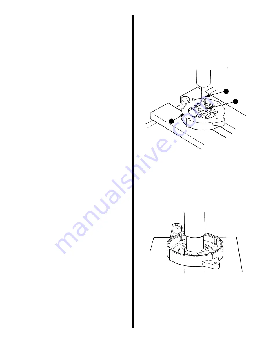
Front Bearing
Removal
1. Remove snap ring.
2. Use an arbor press to remove bearing from hous-
ing.
73093
a - Front Housing
b - Bearing Driver
c - Bearing
b
c
a
Installation
1. Using an arbor press, press on outer race of new
bearing until fully seated in housing.
73094
a - Press
b - Mandrel
2. Install snap ring to retain bearing.
Summary of Contents for 13
Page 1: ...13 Printed in U S A 90 816462 2 695 1995 Brunswick Corporation GM 4 Cylinder MARINE ENGINES ...
Page 2: ...90 816462 2 695 0 ...
Page 7: ...1 A IMPORTANT INFORMATION GENERAL INFORMATION 72000 ...
Page 15: ...1 B 50617 IMPORTANT INFORMATION MAINTENANCE ...
Page 36: ...1 C IMPORTANT INFORMATION TROUBLESHOOTING ...
Page 74: ...2 A 50633 REMOVAL AND INSTALLATION 4 CYL ALPHA ONE DRIVE ...
Page 88: ...3 A 26790 ENGINE 181 CID 3 0L 4 CYLINDER GM ENGINE ...
Page 137: ...4 A 72079 ELECTRICAL SYSTEMS STARTING SYSTEM ...
Page 170: ...4 B 71855 ELECTRICAL SYSTEMS IGNITION SYSTEM ...
Page 197: ...ELECTRICAL SYSTEMS CHARGING SYSTEM 4 C 72078 ...
Page 237: ...4 D 72747 ELECTRICAL SYSTEMS INSTRUMENTATION ...
Page 250: ...4 E 72938 ELECTRICAL SYSTEMS WIRING DIAGRAMS ...
Page 264: ...5 A FUEL SYSTEM FUEL PUMP ...
Page 271: ...5 B 72681 FUEL SYSTEM MERCARB 2 BARREL CARBURETOR ...
Page 300: ...6 A 50628 COOLING SYSTEM SEAWATER COOLED MODELS ...
Page 309: ...6 B 73665 COOLING SYSTEM CLOSED COOLING MODELS ...
Page 325: ...C 6 EXHAUST SYSTEM MANIFOLD ...
Page 331: ...7 A 71317 POWER STEERING PUMP ...


