background image

S160/S161/S165/Z162

8-13

Maintenance

8

2

3

4

1

2

1

1

3

Figure 8-28

NOTE

-

The bucket arm must be in the lowest position.

-

The quick-change device must be tipped and
the locking bolts extended with the hand lever
for the auxiliary hydraulics (4-6/5).

-

The oil level must be visible in the upper
quarter of the view glass.

(12) Close the filler neck with the special tool (flat open-
ended spanner).

8.2.9

Replacing the suction return flow filter

cartridge

CAUTION

Replace the filter insert according to the
maintenance plan or when the clogging indicator
lamp (4-10/13) lights up.

NOTE

The clogging indicator may light up prematurely
after a cold start. It will go out when the hydraulic
oil warms up.

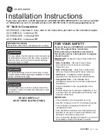
(1) Unscrew the maintenance plate (8-28/arrow).
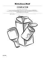
(2) Undo the hose clamp on the rubber bellows (8-29/3)
and pull of the bellows.
(3) Loosen but do not unscrew both screws of the
hydraulic oil filter lid (8-29/1).
(4) Lift out the hydraulic oil filter lid with the magnetic tube
(8-30/2).
(5) Swing up the handle (8-30/3), pull out the filter
cartridge (8-30/4) and replace it with a new one.

CAUTION

The used hydraulic oil filter cartridge must be
disposed of in such a way that it does not cause
pollution.

(6) Use a clean cloth to wipe the magnet tube (8-30/2)
before fitting it back in.
(7) Refit the hydraulic oil filter lid with magnet tube and
fasten it again.
(8) Connect the ventilation hose to the ventilation valve
(8-29/2 or 8-30/1).
(9) Start the engine.
(10) Have an oil drain pan ready and open the ventilation
valve.

N O T E

Keep the ventilation valve open until there are no
more bubbles in the escaping oil.

(11) Close the ventilation valve.
(12) Push the rubber bellows (8-29/3) on the air filter hose
and fasten it with the hose clamp.
(13) Screw the maintenance plate (8-28/arrow) back on.

Figure 8-29

Figure 8-30

Summary of Contents for AS 150e

Page 1: ...Maintenance...

Page 2: ...g unit Air filter Air conditioning unit 12 1 Perform functional check before starting work 12 2 Check air filter 12 3 Visual check air conditioning unit 12 4 Check condensator for contamination 12 5 C...

Page 3: ...blocked 1 4 arrow Theloadermustbesecuredagainstrollingby applying the parking brake 4 7 4 and by setting the drive direction switch 4 7 3 to position 0 In addition wheel chocks must be placed on both...

Page 4: ...el must reach the plug bores If necessary top up oil Collect any oil that escapes 2 Screw in the plug again 8 2 2 2 Planetary gear 1 Move the loader until the marking line OIL LEVEL is horizontal and...

Page 5: ...per oil compartment coupling space 4 Unscrew the plug 8 6 4 from the lower oil compart ment spur gear space NOTE The loader must have been standing still for at least 15 minutes before you can check t...

Page 6: ...and 8 9 2 from the lower oil compartment spur gear compartment NOTE The loader must have been standing still for at least 15 minutes before you can check the oil level The transmission housing temper...

Page 7: ...f the view glass If necessary top up hydraulic oil via the filler neck 8 11 arrow Use the special tool flat open ended spanner to undo the lid of the hydraulic oil tank 8 2 5 Oil change engine 1 Unscr...

Page 8: ...eplacetheplugsfortheaxlearch 8 13 1 8 13 2and 8 13 3 4 Fill oil into the plug bore of the axle arch 8 13 4 or 8 14 arrow until the oil level reaches the opening NOTE Details regarding the amount of oi...

Page 9: ...the marking line OIL LEVEL is horizontal and the plug is located above the top left of the marking line 8 17 arrow 5 Fillinoilviatheplugboreuntiltheoillevelreachesthe opening 6 Use a new gasket when...

Page 10: ...le Theventvalveoftheaxle 8 20 arrow mustbe free from dirt 5 Screw the plugs 8 18 4 and 8 19 arrow back in 8 2 7 Oil change distribution gear 8 2 7 1 Oil change distribution gear Type 1 1 Remove the fo...

Page 11: ...in with new gaskets 8 2 7 2 Oil change distribution gear Type 2 1 Open battery and tool compartment on the left side of the loader 2 Movethebucketarmallthewaytotheleftorrightand removethefrontcoverpla...

Page 12: ...oil drain plug 8 25 arrow 4 Screwthedrainagenozzlewithhosefromthetoolbox 4 1 13 to the oil drain plug 5 Remove the cover cap from the hose 6 Drain the oil into the oil vessel CAUTION Waste oil must be...

Page 13: ...ull of the bellows 3 Loosen but do not unscrew both screws of the hydraulic oil filter lid 8 29 1 4 Liftoutthehydraulicoilfilterlidwiththemagnetictube 8 30 2 5 Swing up the handle 8 30 3 pull out the...

Page 14: ...ly long to reach the bottomofthecartridge Usedrycompressedair of no more than 5 bar to blow out the car tridge by moving the pipe back and forth in the interior of the cartridge Cleaning can be stoppe...

Page 15: ...perating instructions for the engine 8 2 13 Replacing the starter batteries NOTE The starter batteries are maintenance free according to DIN 72311 section 7 They are located on the left side of the ca...

Page 16: ...compressed air CAUTION Do not use any petrol hot fluids or industrial compressed air for cleaning 4 Check the filter elements for damage NOTE The filter elements must be replaced when they are damage...

Page 17: ...ase the rear axle from load before lubricating the rear axle pivot bolts 8 3 2 Rear axle 8 41 arrows CAUTION The spindle bolts must be lubricated every 50 operating hours NOTE Lubricate the top and th...

Page 18: ...nger period of inactivity DANGER Before you start lubricating mechanically support the bucket arm e g by inserting the bucket arm support optional 1 1 arrow apply the parking brake 4 7 4 and set the d...

Page 19: ...CAUTION The leverage of the supporting valve actuator must be lubricated with engine oil every 50 operating hours 1 Liftthebucketarm insertthebucketarmsupportand swivel the bucket arm all the way to t...

Reviews: