


The “
MBRAUN
QuickPurge” automatic purging system is an optional component for comfortably operating
the system.
Caution!
Annoyance by bad smell is expected as soon as any used-up purge gas escap
es
to the
surroundings. Environmental pollution and effects detrimental to health, however, are not known,
but cannot be excluded. The manufacturer does not assume any liability!
When using toxic or radioactive material
,
a special purging facility is required!
Prerequisites:
Having observed all previous chapters.
All connections have been properly made.
The working gas connection has been made, refer to chapter 3 “Preparations for Connections” and
chapter 4 “Installation”.
The
exhaust
line for used-up purge gas has been made, refer to Chapter 3 “Preparations for Connec-
tions” and Chapter 4 “Installation”.
The material for manual purging has been provided, refer to chapter 3 “Preparations for connections”
The system is activated, refer to chapter 5 “Activating the system”
The system functions “Circulation” and “ Regeneration” are not activated.
All antechambers are in closed position.
Sufficient working gas ( = purge gas) is available - Required quantity approx. 8
,
000 to 10
,
000 m
3
for
1 m
3
box volume each.
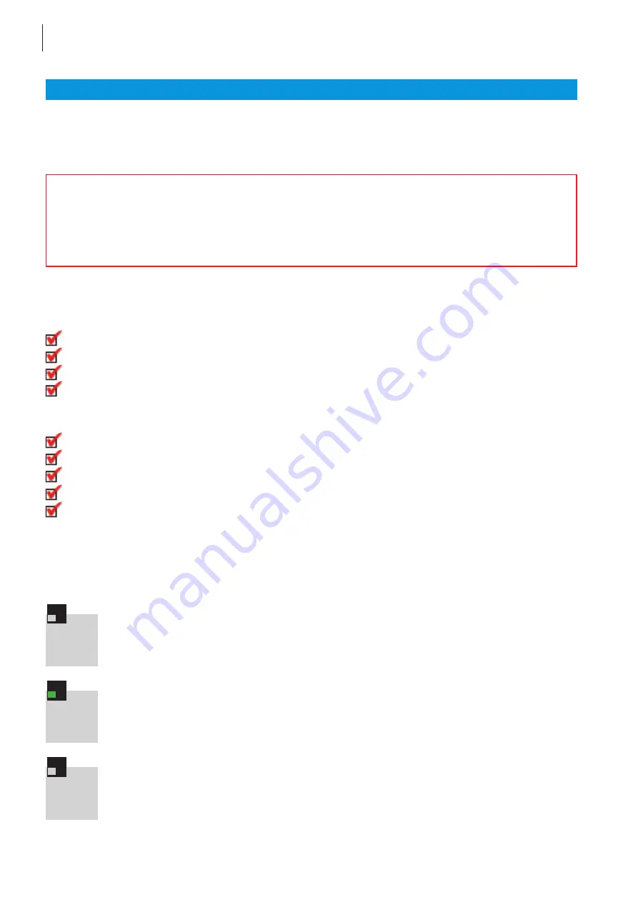
Purging procedure
Press “Quick purge” Hardkey on the OP17 Operation Panel.
Status indicator illuminated green.
Purge box until an oxygen value of smaller than 100 ppm has been obtained.
Press “Quick purge” hardkey.
Status indicator not illuminated - purging procedure completed.
!
Chapter 7
Purging the System
36
“MBRAUN QuickPurge” automatic purging system
Quick
purge
Quick
purge
Quick
purge
Summary of Contents for MB 120B-G
Page 6: ...OPERATING INSTRUCTIONS Chapter 1 General Information MBRAUN 1...
Page 10: ...OPERATING INSTRUCTIONS Chapter 2 Transport Site Selection Modification MBRAUN 2...
Page 13: ......
Page 14: ...OPERATING INSTRUCTIONS Chapter 3 Preparing the Connections MBRAUN 3...
Page 20: ...OPERATING INSTRUCTIONS Chapter 4 Installation MBRAUN 4...
Page 24: ...OPERATING INSTRUCTIONS Chapter 5 Activating and Deactivating the System MBRAUN 5...
Page 28: ...OPERATING INSTRUCTIONS Chapter 6 OP 17 Operation Panel MBRAUN 6...
Page 32: ...OPERATING INSTRUCTIONS Chapter 7 Purging the System MBRAUN 7...
Page 36: ...OPERATING INSTRUCTIONS Chapter 8 Pressure Control System MBRAUN 8...
Page 40: ...OPERATING INSTRUCTIONS Chapter 9 Circulation Mode MBRAUN 9...
Page 45: ......
Page 46: ...OPERATING INSTRUCTIONS Chapter 10 Regeneration MBRAUN 10...
Page 51: ......
Page 52: ...OPERATING INSTRUCTIONS Chapter 11 Settings and Display Patterns MBRAUN 11...
Page 59: ......
Page 60: ...OPERATING INSTRUCTIONS Chapter 12 Antechamber Operation MBRAUN 12...
Page 73: ......
Page 74: ...OPERATING INSTRUCTIONS Chapter 13 Dust Filters MBRAUN 13...
Page 77: ......
Page 78: ...OPERATING INSTRUCTIONS Chapter 14 Analyzers MBRAUN 14...
Page 90: ...OPERATING INSTRUCTIONS Chapter 15 Maintenance and Service MBRAUN 15...
Page 94: ...OPERATING INSTRUCTIONS Chapter 16 Spare Parts List MBRAUN 16...
Page 103: ......
Page 105: ......


