3-6
DISPLAY DEFINITIONS
www.maxcessintl.com
FIFE-500-XL
MI 2-267 1 D
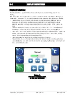
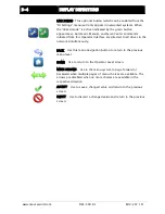
GUIDE POINT CHANGED This icon appears when a new System
Guidepoint has been applied. This icon will appear on the status bar
until the System Guidepoint remains unchanged for approximately 20
seconds.
EXTERNAL LOCK This icon indicates the acceptance of the “External
Lock” digital input command. Automatic guide movement is prohibited
while in this state.
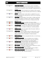
ASC ON Automatic Sensor Control (ASC) is enabled for the current
sensor mode. See the menu description for ASC for more information
about ASC operation.
ASC ACTIVE Automatic Sensor Control (ASC) is enabled and the ASC
state has been triggered. Automatic guide movement is prohibited.
See the menu description for ASC for more information about ASC
operation.
MOTOR BLOCKED This icon indicates the motor is stalled.
COMMUNICATION ERROR This error icon indicates communication is
not working between the operator interface and the motor controller.
VOLTAGE ERROR This error icon appears when the input voltage,
motor rail voltage, or internal 12 volt power is outside acceptable
range.
NETWORK ERROR This icon appears when the operator interface is
unable to gain network control.
LINKED MODE This icon appears when the “linked mode” is active.
Linked mode is used in networked systems to send the Automatic,
Manual, and Servo Center commands to all network devices
simultaneously.
MOTOR TYPE FAULT This icon appears when there is no motor type
configured.
COMMUNICATION FAULT This icon appears when a problem is
detected with the communication signals. This can be caused by
hardware or an addressing conflict in a networked system.
LINE SPEED ZERO This icon appears when line speed control is
enabled and the sensed line speed is zero. Guide correction is
inhibited in Automatic mode under these conditions.
MCP-05 SEEK If the MCP-05 option has been enabled, this icon will
blink while a seek operation is in progress.
MOTOR ENCODER FAULT This icon appears when a problem is
detected with the encoder signals from the motor.
MOTOR HALL STATE FAULT This icon appears when a problem is
detected with the motor hall state transitions.

