3-3
DISPLAY DEFINITIONS
www.maxcessintl.com
FIFE-500-XL
MI 2-267 1 D
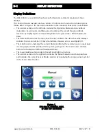
Button Functions and Definitions
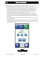
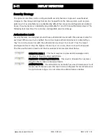
AUTOMATIC Initiates the Automatic mode. Correction is applied
to the web by moving the guide in response to the output of the
sensor(s) that have been selected.
SERVO-CENTER Initiates the Servo-Center mode. The guide is
centered in its travel in response to the output of the internal
Servo-Center transducer.
MANUAL Initiates the Manual mode. No correction is applied to
the guide.
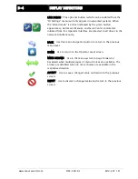
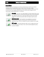
SENSOR Use to select the sensor(s) to be used for monitoring the
web position when the system is in Automatic mode. Sensor
selection is allowed in Manual and Servo-Center modes only.
SETUP Use to enter the Setup Menus for configuring and adjusting
the guiding system.
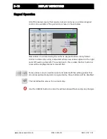
ARROWS Use these buttons to jog the guide. The direction of
guide movement is configurable.
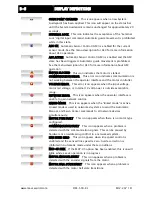
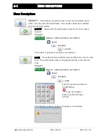
GUIDE POINT CONTROL Use the two arrow buttons to adjust the
System Guide Point while in Automatic Mode or Manual Mode. Use
the center button to reset the System Guide Point to the default
value, which is 50% of the sensor bandwidth. The slider control
indicates the guide point position. The color of the guide point
pointer is blue when the guide point is zero, yellow when a guide
point shift is present and red when the guide point shift has
reached either extreme.
GUIDE POINT CAPTURE This optional button (which can be enabled
from the “OI Settings” menu) sets the guide point of the active
sensor mode to the current web location. This allows guiding to
begin at the current web location when the Automatic mode is
initiated.
DRIVE SELECT This button will only appear in networked systems.
When available, it displays a list of available drives in the network
and allows the OI to be switched directly to any of them.
DRIVE SELECT These buttons will only appear in networked
systems. When available, they allow the operator interface to be
connected to the previous or next sequential drive in the network.


