2. INTAKE VALVE SEAT: Cutting sequence is the same as for
exhaust valve seats.
Seat width for intake valve seat:
1.1 – 1.3 mm (0.0433 – 0.0512 in.)
3. VALVE LAPPING: Lap valve on seat in two steps, first with
coarse size lapping compound applied to face and the se-
cond with fine-size compound, each time using valve lapper
according to usual lapping method.
Cylinder Head
Remove all carbon from combustion chambers.
NOTE:
Do not use any sharp-edged tool to scrape off carbon. Be
careful not to scuff or nick metal surfaces when decarbon-
ing. The same applies to valves and valve seats, too.
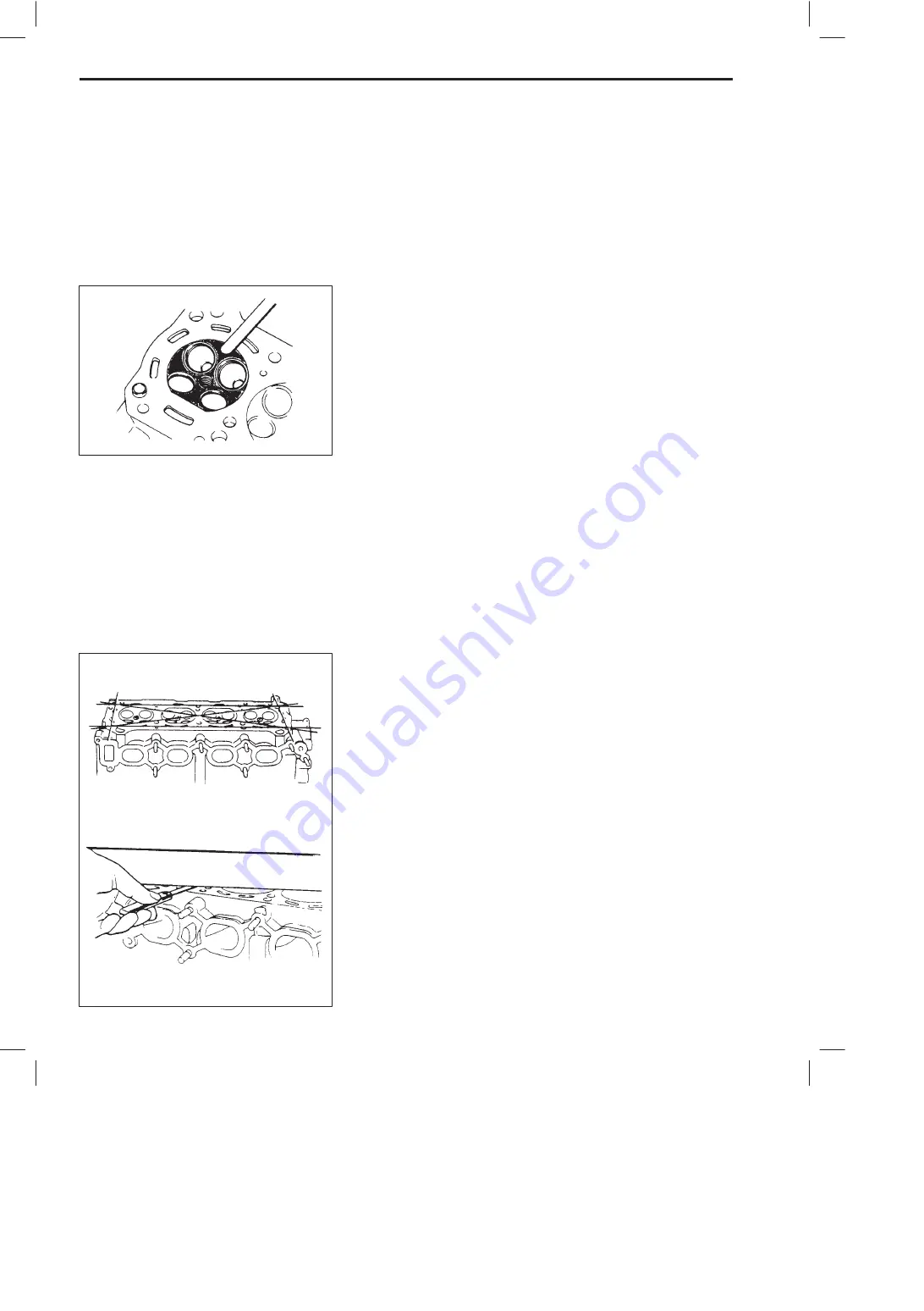
Check cylinder head for cracks in intake and exhaust ports, com-
bustion chambers, and head surface.
Flatness of gasketed surface:
Using a straightedge and thickness gauge, check surface at a
total of 6 locations. If distortion limit, given below, is exceeded,
correct gasketed surface with a surface plate and abrasive pa-
per of about #400 (Waterproof silicon carbide abrasive paper):
place paper on and over surface plate, and rub gasketed surface
against paper to grind off high spots. Should this fail to reduce
thickness gauge readings to within limit, replace cylinder head.
Leakage of combustion gases from this gasketed joint is often
due to warped gasketed surface: such leakage results in re-
duced power output.
Limit of distortion: 0.05 mm (0.002 in.)
6A1-44
ENGINE MECHANICAL
SH410


