background image

Using LCS

 15

Options menu

R e a d   F i r m w a r e   ( t o   F I R M _ U P D _ * * . B I N )

This option copies firmware from a selected panel to the “lcs” 
folder on the PC’s C drive. The firmware can then be installed on 
other panels. This is useful if some panels have outdated 
firmware but there is no convenient Internet access.

Service technicians with access to an EEPROM burner can use 
the file to make a copy of the panel’s EEPROM, including calibration values. 

To copy firmware from a panel to the PC:

1. In the grid display, click the panel to copy from. 

2. Select Options > Read Firmware (to FIRM_UPD_**.BIN) from the main menu. 

3. Allow the process several minutes to complete.

4. To confirm the operation, verify that the firmware is located in the lcs folder. 

U p d a t e   F i r m w a r e   ( t o   o n e   p a n e l )

This option installs firmware on the currently selected panel. 

To install firmware in a single panel:

1. Download the firmware update from the Support Area of the Martin

® 

web site at www.martin.com and 

save it in the C:/lcs folder. 

2. Click in the grid display to select a panel to update.

3. Select Options > Update Firmware (to one unit) from the menu.

4. Click the firmware file to install. Click Open.

5. At the panel reset prompt, click Yes or No

6. The panel will flicker and the progress indicator rotates during the update. When the update is 

completed, LCS writes “Finish, please connect after 20 sec.” Wait 20 seconds and press Connect

U p d a t e   F i r m w a r e   t o   a l l   p a n e l s

This options installs firmware on all panels. 

To install firmware:

1. Download the firmware file from the Support Area of 

the Martin

® 

web site at www.martin.com and save it in 

the C:/lcs folder. 

2. Select Options > Update Firmware to all panels 

from the menu.

3. Click the firmware file to install. Click Open

4. At the “Overwrite all, or only older versions?” prompt, 

click No unless you are installing an older version of 
firmware. 

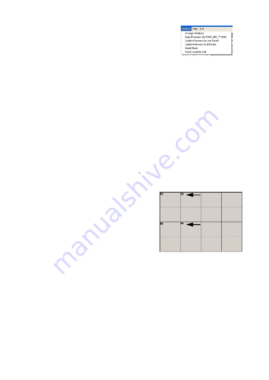
5. The update occurs one panel at a time. The panel’s 

firmware version number is displayed while the update 
is in progress and underlined when completed. When 
all panels are updated, LCS writes the message “--finish--”. 

6. Press the Connect button to refresh the grid display. 

R e s e t   P a n e l

This option resets the selected panel with the settings stored in the panel’s non-volatile memory. Unsaved 
settings will be lost. 

R e s e t   c o m p l e t e   W a l l

This option resets all panels. Resetting is recommended after making settings changes to confirm that the 
settings have been saved. 

Figure 20: Options menu

Figure 21: Firmware update progress

update complete

update in 
progress

Summary of Contents for DVI Buffer Box

Page 1: ...DVI Buffer Box for LC Series Video Screen user manual...

Page 2: ...ssion in writing from Martin Professional A S Information subject to change without notice Martin Professional A S and all affil iated companies disclaim liability for any injury damage direct or indi...

Page 3: ...nu 15 Troubleshooting 16 DVI Buffer Box specifications 17 Disposing of this product Martin products are supplied in compliance with Directive 2002 96 EC of the European Parliament and of the Council o...

Page 4: ...d by the PC or Maxedia media server Genlock synchronization with other video devices Interface between panels and LCS the LC series panel management PC software About LCS The LC software allows the us...

Page 5: ...anel Connect with video devices powered off BNC term jumper Provides BNC cable termination Used when the DVI Buffer Box is the last device on the cable 60 Hz jumper Selects 60 Hz monitor emulation 50...

Page 6: ...ices via an external synchronization signal connected to the DVI Buffer Box A composite video signal or master sync pulse signal may be used When using an external signal connect the cable from the si...

Page 7: ...or Exit Setup if you need to go back 5 The next dialog prompts you for the installation destination The default location is C Program Files lcs To select another location click Change Directory 6 Cli...

Page 8: ...mportant usage tips H o w to c h an g e nu m e r ic v alu e s In LCS you change numeric values by moving the PC s pointing device a trackball is recommended while holding down the left button as follo...

Page 9: ...determine the number of cells in the grid display The Origin fields determine the XY coordinates of the top left cell which are 0 0 by default Change the values as described on page 8 under How to ch...

Page 10: ...allow change the XY coordinates of the video wall with the addressing controls A d dr e ss in g c o nt r o ls Show Addresses button Clicking Show Addresses freezes the video output and displays the XY...

Page 11: ...itch erases the software set address and returns the selected panel to its DIP switch set address To return a panel to its DIP address 1 In the grid display click the desired panel 2 Click DIP Switch...

Page 12: ...anel 6 Using the same fill color repeat the process for each panel that needs adjustment 7 Repeat for the other fill colors 8 When all adjustments have been made click Save Parameters to save the pane...

Page 13: ...n the grid display 2 Select a signal source DVI or External Vsync 3 For genlock synchronization remove the check from the Phase Off check box When checked panels are frequency tuned only 4 Click Tune...

Page 14: ...temperature of the LC panels DSP circuit boards in the grid display Significantly higher temperature in one panel probably indicates a defective cooling fan which must be replaced Fa n C o o l i ng r...

Page 15: ...5 At the panel reset prompt click Yes or No 6 The panel will flicker and the progress indicator rotates during the update When the update is completed LCS writes Finish please connect after 20 sec Wai...

Page 16: ...ther device connected to COM port 1 to 4 Test system without other devices connected to COM ports 1 4 Assign the conflicting to device to COM port 5 or higher Some panels respond to LCS some do not Th...

Page 17: ...n BNC Th e r m a l Maximum ambient temperature Ta max 40 C 104 F Minimum ambient temperature Ta min 0 C 32 F A p p r o v a l s EU safety EN 60950 EU EMC EN 55022 EN 55024 EN 61000 3 2 EN 61000 3 3 I n...

Page 18: ......

Page 19: ......

Page 20: ......

Reviews: