background image

 12

DVI Buffer Box user manual

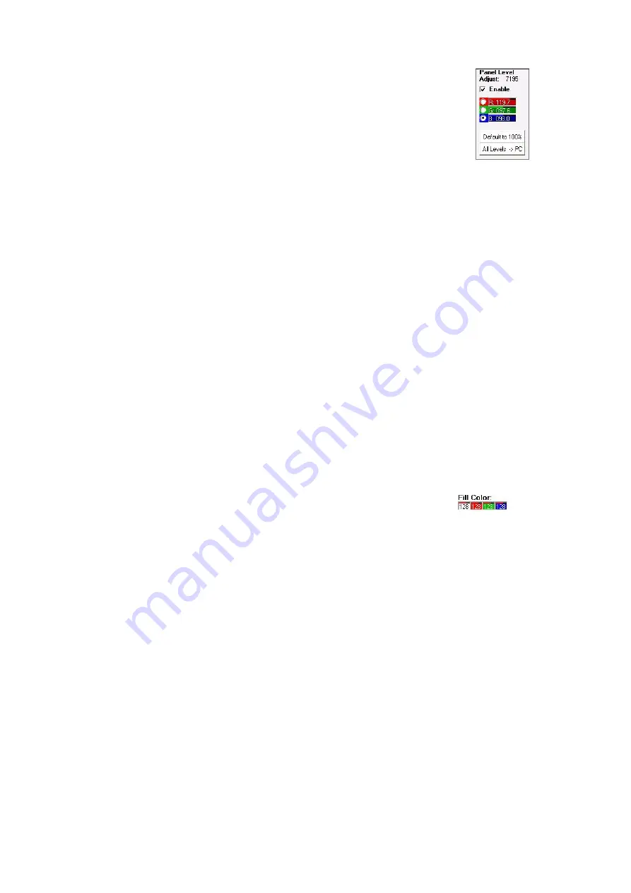
P a n e l   L e v e l   A d j u s t  

The Panel Level Adjust function allows you to adjust the color levels in 
individual panels to compensate for differences in performance. 

The red, green, and blue fields display the brightness levels for the 
selected panel. The values can be refreshed by clicking Connect or the 
All Levels > PC button. The radio buttons are not intended to be clicked. 
Use the Fill Color fields instead to select the color to adjust. 

To adjust individual panel levels:

1. Select red, green, or blue using the Fill Color fields. Do not select the 

white fill color. 

2. Place a check in the Panel Level Adjust Enable check box. 

3. An on-panel cursor appears when the panel level adjust function is enabled. Use the trackball 

(recommended) or other pointing device to select a panel.

4. With the cursor on the desired panel, hold the left button down and move the pointing device up or right 

to increase the color intensity, or down or left to decrease it. Release the left button. 

5. Clicking Default to 100% brings all levels to 100% in the selected panel.

6. Using the same fill color, repeat the process for each panel that needs adjustment. 

7. Repeat for the other fill colors. 

8. When all adjustments have been made, click Save Parameters to save the panel levels in non-volatile 

memory. Remove the check from the Enable check box. 

F r e e z e / R u n   b u t t o n s

The Freeze / Run buttons toggle the video stream on (run mode) and off (freeze mode). Freeze mode is 
required when displaying addresses or using the color fill function. The other commands can be executed in 
run or freeze mode. 

F a c t o r y   D e f a u l t   b u t t o n

Clicking Factory Default returns all panels to LCS default values for wall brightness, pixel position, and 
cooling mode. The settings take effect immediately but are not saved in the panels’ non-volatile memories 
until Save Parameters is pressed. 

F i l l   C o l o r  

The Fill Color fields allow you to fill the screen with a solid color 
for test and adjustment purposes. 

Each control ranges in value from 0 (off) to 255 (full intensity). 
The maximum brightness that can be achieved using the Fill 
Color fields is limited by the Wall Brightness settings. 

Change the color values as described on page 8, under “How to change numeric values”. To clear the fill 
color, click Run.

Figure 14: 

Panel Level Adjust

Figure 15: Fill Colors

Summary of Contents for DVI Buffer Box

Page 1: ...DVI Buffer Box for LC Series Video Screen user manual...

Page 2: ...ssion in writing from Martin Professional A S Information subject to change without notice Martin Professional A S and all affil iated companies disclaim liability for any injury damage direct or indi...

Page 3: ...nu 15 Troubleshooting 16 DVI Buffer Box specifications 17 Disposing of this product Martin products are supplied in compliance with Directive 2002 96 EC of the European Parliament and of the Council o...

Page 4: ...d by the PC or Maxedia media server Genlock synchronization with other video devices Interface between panels and LCS the LC series panel management PC software About LCS The LC software allows the us...

Page 5: ...anel Connect with video devices powered off BNC term jumper Provides BNC cable termination Used when the DVI Buffer Box is the last device on the cable 60 Hz jumper Selects 60 Hz monitor emulation 50...

Page 6: ...ices via an external synchronization signal connected to the DVI Buffer Box A composite video signal or master sync pulse signal may be used When using an external signal connect the cable from the si...

Page 7: ...or Exit Setup if you need to go back 5 The next dialog prompts you for the installation destination The default location is C Program Files lcs To select another location click Change Directory 6 Cli...

Page 8: ...mportant usage tips H o w to c h an g e nu m e r ic v alu e s In LCS you change numeric values by moving the PC s pointing device a trackball is recommended while holding down the left button as follo...

Page 9: ...determine the number of cells in the grid display The Origin fields determine the XY coordinates of the top left cell which are 0 0 by default Change the values as described on page 8 under How to ch...

Page 10: ...allow change the XY coordinates of the video wall with the addressing controls A d dr e ss in g c o nt r o ls Show Addresses button Clicking Show Addresses freezes the video output and displays the XY...

Page 11: ...itch erases the software set address and returns the selected panel to its DIP switch set address To return a panel to its DIP address 1 In the grid display click the desired panel 2 Click DIP Switch...

Page 12: ...anel 6 Using the same fill color repeat the process for each panel that needs adjustment 7 Repeat for the other fill colors 8 When all adjustments have been made click Save Parameters to save the pane...

Page 13: ...n the grid display 2 Select a signal source DVI or External Vsync 3 For genlock synchronization remove the check from the Phase Off check box When checked panels are frequency tuned only 4 Click Tune...

Page 14: ...temperature of the LC panels DSP circuit boards in the grid display Significantly higher temperature in one panel probably indicates a defective cooling fan which must be replaced Fa n C o o l i ng r...

Page 15: ...5 At the panel reset prompt click Yes or No 6 The panel will flicker and the progress indicator rotates during the update When the update is completed LCS writes Finish please connect after 20 sec Wai...

Page 16: ...ther device connected to COM port 1 to 4 Test system without other devices connected to COM ports 1 4 Assign the conflicting to device to COM port 5 or higher Some panels respond to LCS some do not Th...

Page 17: ...n BNC Th e r m a l Maximum ambient temperature Ta max 40 C 104 F Minimum ambient temperature Ta min 0 C 32 F A p p r o v a l s EU safety EN 60950 EU EMC EN 55022 EN 55024 EN 61000 3 2 EN 61000 3 3 I n...

Page 18: ......

Page 19: ......

Page 20: ......

Reviews: