background image

 8

DVI Buffer Box user manual

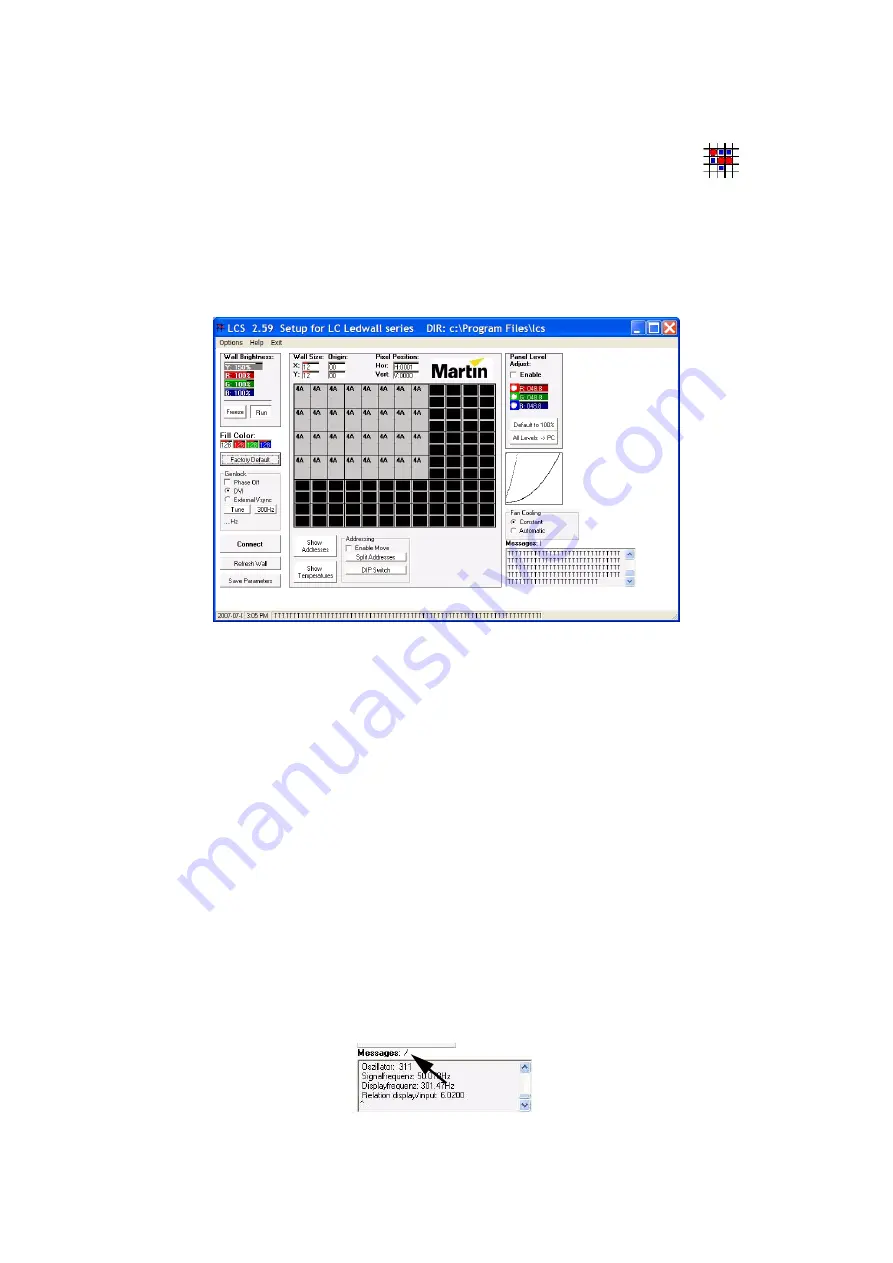
Starting the application

The installation wizard places a shortcut to LCS in your program list. 

To start LCS:

1. Connect the DVI Buffer Box to the computer’s COM port and verify that 

its “DVI com.” LED is lit. 

2. Click the Windows start button, then click All Programs

3. Point to the LCS program group and click the LCS icon. 

4. If starting LCS for the first time, click the Factory Default and 300Hz buttons. 

After starting, LCS automatically detects connected panels and displays their firmware version numbers in 
the grid display. If no version numbers appear in the grid display, check all connections and verify that the 
DVI Buffer Box is connected. 

Important usage tips

H o w   t o   c h a n g e   n u m e r i c   v a l u e s

In LCS, you change numeric values by moving the PC’s pointing device (a trackball is recommended) while 
holding down the left button as follows: 

1. Place the cursor over the field to modify.

2. Hold down the left button of the pointing device. 

3. Move the pointing device up or to the right to increase the value, or down or to the left to decrease the 

value.

4. Release the left button. 

A l l o w   c o m m a n d s   t o   e x e c u t e

Commands must be allowed to execute before launching new commands. Execution is indicated by rotation 
of the line above the Messages field. Wait until rotations stops before continuing.

Tip: To minimize the time it takes to execute commands, set the wall size (see page 9) to the minimum 
required to display the video curtain. 

Figure 5: LCS icon

Figure 6: LCS screen

Figure 7: Execution status indicator

Summary of Contents for DVI Buffer Box

Page 1: ...DVI Buffer Box for LC Series Video Screen user manual...

Page 2: ...ssion in writing from Martin Professional A S Information subject to change without notice Martin Professional A S and all affil iated companies disclaim liability for any injury damage direct or indi...

Page 3: ...nu 15 Troubleshooting 16 DVI Buffer Box specifications 17 Disposing of this product Martin products are supplied in compliance with Directive 2002 96 EC of the European Parliament and of the Council o...

Page 4: ...d by the PC or Maxedia media server Genlock synchronization with other video devices Interface between panels and LCS the LC series panel management PC software About LCS The LC software allows the us...

Page 5: ...anel Connect with video devices powered off BNC term jumper Provides BNC cable termination Used when the DVI Buffer Box is the last device on the cable 60 Hz jumper Selects 60 Hz monitor emulation 50...

Page 6: ...ices via an external synchronization signal connected to the DVI Buffer Box A composite video signal or master sync pulse signal may be used When using an external signal connect the cable from the si...

Page 7: ...or Exit Setup if you need to go back 5 The next dialog prompts you for the installation destination The default location is C Program Files lcs To select another location click Change Directory 6 Cli...

Page 8: ...mportant usage tips H o w to c h an g e nu m e r ic v alu e s In LCS you change numeric values by moving the PC s pointing device a trackball is recommended while holding down the left button as follo...

Page 9: ...determine the number of cells in the grid display The Origin fields determine the XY coordinates of the top left cell which are 0 0 by default Change the values as described on page 8 under How to ch...

Page 10: ...allow change the XY coordinates of the video wall with the addressing controls A d dr e ss in g c o nt r o ls Show Addresses button Clicking Show Addresses freezes the video output and displays the XY...

Page 11: ...itch erases the software set address and returns the selected panel to its DIP switch set address To return a panel to its DIP address 1 In the grid display click the desired panel 2 Click DIP Switch...

Page 12: ...anel 6 Using the same fill color repeat the process for each panel that needs adjustment 7 Repeat for the other fill colors 8 When all adjustments have been made click Save Parameters to save the pane...

Page 13: ...n the grid display 2 Select a signal source DVI or External Vsync 3 For genlock synchronization remove the check from the Phase Off check box When checked panels are frequency tuned only 4 Click Tune...

Page 14: ...temperature of the LC panels DSP circuit boards in the grid display Significantly higher temperature in one panel probably indicates a defective cooling fan which must be replaced Fa n C o o l i ng r...

Page 15: ...5 At the panel reset prompt click Yes or No 6 The panel will flicker and the progress indicator rotates during the update When the update is completed LCS writes Finish please connect after 20 sec Wai...

Page 16: ...ther device connected to COM port 1 to 4 Test system without other devices connected to COM ports 1 4 Assign the conflicting to device to COM port 5 or higher Some panels respond to LCS some do not Th...

Page 17: ...n BNC Th e r m a l Maximum ambient temperature Ta max 40 C 104 F Minimum ambient temperature Ta min 0 C 32 F A p p r o v a l s EU safety EN 60950 EU EMC EN 55022 EN 55024 EN 61000 3 2 EN 61000 3 3 I n...

Page 18: ......

Page 19: ......

Page 20: ......

Reviews: