


6
DVI Buffer Box user manual
D V I v i d e o c o n n e c t i o n
The DVI Buffer Box accepts a 1024 x 768 XGA DVI-D single link
(digital and DDC) signal.
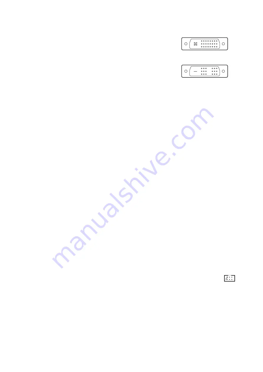
It has two DVI connectors: one for input and one for output. Although
the video signal is DVI-D single link, the connectors are DVI-I dual
link type. The advantage of this solution is that any DVI cable can be
used, although only the pins that carry the DVI-D single link signal
are actually used.
The DVI Buffer Box is powered by the 5 V power line in the DVI input
cable. The “DVI Com.” LED lights when the device is receiving
power.
Up to 6 panels may be connected in series (daisy-chained) to the
DVI output in first generation. For more information regarding DVI
link configuration, please refer to the LC 1140/2140 LED Video
Screen user manual.
To connect the DVI signal:
1. Power all panels and devices off while making connections.
2. Use a short (1.5 m) DVI-D cable to connect the DVI output from the source (Martin Maxedia, for
example) to the DVI Buffer Box input.
3. Use a short (1.5 m) or medium length (3.2 m) DVI-D cable to connect the DVI output from the DVI Buffer
Box to the first panel or splitter. The total DVI-D cable length from the video source to the first panel or
splitter may not exceed 5 m (16 ft.)
G e n l o c k c o n n e c t i o n
The video curtain can be synchronized with other video devices via an external synchronization signal
connected to the DVI Buffer Box. A composite video signal or master sync pulse signal may be used.
When using an external signal, connect the cable from the signal source or previous video device to the
BNC terminal. You will need a cable splitter (T-connector, not included) if the signal must be fed to additional
devices.
Select a BNC termination option as described below, under “Jumper settings”.
P C c o n n e c t i o n
The DVI Buffer Box communicates with the LC software through the PC’s serial (COM) port. To connect the
DVI Buffer Box to a PC, connect the included serial cable to the RS-232 port on the buffer box and a COM
port from 1 to 4 on the PC. LCS automatically detects the hardware when it starts up.
The serial cable connects pins 2, 3, and 5 on each end. Tip: If a longer serial cable is needed, use a
shielded data cable with the shield connected to pin 5 on each end.
No documentation or support is available for the selection or use of an accessory serial port adaptor.
J u m p e r s e t t i n g s
DVI signal frequency and BNC cable termination are selected with the jumpers on the DVI Buffer Box. Set
as follows.
• Place one jumper cap on either the 50 Hz or 60 Hz jumper to match the frequency of the DVI source.
• If the DVI Buffer Box is the last device connected to the sync cable, place a jumper cap on the
“BNC term.” jumper. When not used, store the termination jumper cap by placing it on one pin
as shown to right.
Figure 2: DVI connectors
DVI-I dual link connector
DVI-D single link pins
Summary of Contents for DVI Buffer Box
Page 1: ...DVI Buffer Box for LC Series Video Screen user manual...
Page 18: ......
Page 19: ......
Page 20: ......


