


MLA System
USER GUIDE
MLA System
User Guide V2.1
327
…
…
…
…
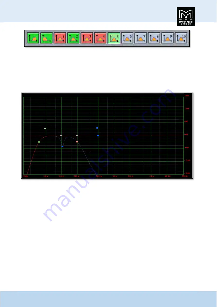
As you can see there are a number of colour variations for these buttons. Unused bands are pale blue until they are selected for
editing by clicking on them in which case the colour goes to a brighter blue and the image shows the button depressed. Unused
is defined as the gain left at 0dB. A red button indicates that the band has been bypassed, irrespective of whether any gain
change has been made. Bypassed bands will change to a pale red when selected. Green buttons indicate a band that has either
cut or boost applied, these will go a pale green when selected. Note that the high pass filter is always active so will always appear
green.
The graphic view of the equalisation is a relatively standard frequency response graph;-
The horizontal axis is frequency in Hertz from 20Hz to 20KHz, the vertical axis is gain from -18dB up to +18dB. Colour coding is
also used on the graph to represent the various modes.
First there are two traces, one red, and the other blue. The red trace is the response of the band that is currently selected; the
blue trace is the overall response of the entire PEQ.
Each small rectangle represents the position of each of the ten bands plus the high pass. For all of the EQ bands the position on
the horizontal represents the EQ centre frequency, the vertical position is the cut or boost applied. A blue rectangle is an active
EQ, a grey rectangle is an EQ that has been bypassed. The green rectangle identifies the cut-off frequency of the highpass filter,
the red rectangle the low pass filter (Sub EQ only).
In common with most PC controlled equalisation systems it is possible to make adjustments by dragging and dropping the filter
curves. Left-click on any of the band rectangles and holding down the left mouse button, drag the icon horizontally to change
the centre frequency or vertically to change the gain. Right-click and drag up and down to adjust the filter Q factor on any of the
peak or shelving bands. The graph will adjust and the audio adjustment will be made in real time.
The final section on the right of the window is the Properties panel;-
Summary of Contents for MLA
Page 1: ...User Guide Multi cellular Loudspeaker Array MLA ...
Page 115: ...MLA System USER GUIDE MLA System User Guide V2 1 115 ...
Page 117: ...MLA System USER GUIDE MLA System User Guide V2 1 117 ...
Page 152: ...MLA System USER GUIDE MLA System User Guide V2 1 152 This is the response on the ceiling ...
Page 215: ...MLA System USER GUIDE MLA System User Guide V2 1 215 ...
Page 258: ...MLA System USER GUIDE MLA System User Guide V2 1 258 ...
Page 413: ...MLA System USER GUIDE MLA System User Guide V2 1 413 ...
Page 420: ...MLA System USER GUIDE MLA System User Guide V2 1 420 ...
Page 421: ...MLA System USER GUIDE MLA System User Guide V2 1 421 ...
Page 438: ...MLA System USER GUIDE MLA System User Guide V2 1 438 ...
Page 440: ...MLA System USER GUIDE MLA System User Guide V2 1 440 ...
Page 447: ...MLA System USER GUIDE MLA System User Guide V2 1 447 ...
Page 454: ...MLA System USER GUIDE MLA System User Guide V2 1 454 ...
Page 455: ...MLA System USER GUIDE MLA System User Guide V2 1 455 The finshed 6 box ground stack system ...


