Marsh PatrionPlus Technical Manual Download Page 207


Repair


29669/02080 Rev AF


7-23


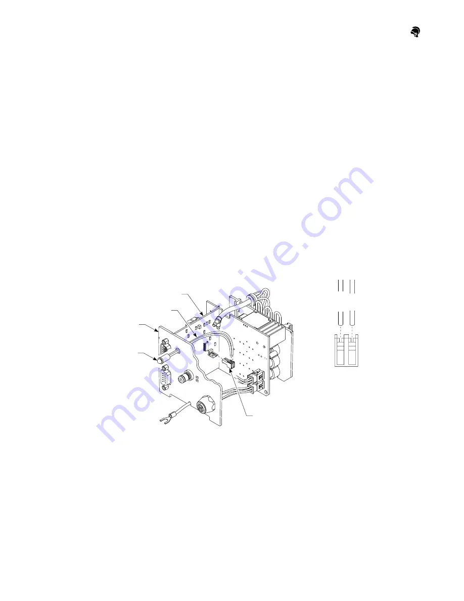
7) Disconnect the LED connector from the CPU board. (See Figure 7V.)

8) Remove the connector from the LED wires.

9) Remove the LED and wires through the back plate.

10) Install the new LED and the wires through the back plate.

11) Install the connector onto the LED wires.

12) Place the new LED connector in the appropriate location on the CPU 

board. (See Figure 7V.)

13) Replace the printhead assembly into the printhead enclosure.

14) Replace the printhead cover.

15) Tighten the four screws on the printhead cover.

16) Secure the printhead ground wire to the printhead bracket with the 

screw.

17) Reconnect the ink line, data lines, and power cables to the back of the 

printhead.

18) Turn on the printhead power supply.


Figure 7V: Replacing the LED

Back Plate

LED Wires

CPU Board

Black

Red

LED

LED Connector

Top View of

LED Connector

Pin Assignments

1     2

Note: Some components have been
removed for illustration purposes.

Summary of Contents for PatrionPlus

Page 1: ...echnologies Inc Wood Dale IL 60191 U S A Tel 618 234 1122 Tel 800 527 6275 Fax 618 234 1529 Videojet Technologies Inc 2002 All Rights Reserved Marsh is a registered trademark of Videojet Technologies...

Page 2: ...l ask for this information Technical Support Telephone U S and Canada 800 851 3441 Telephone International 618 234 9093 All FAX 618 234 1265 E mail Blvl TechSupport videojet com Note If you have more...

Page 3: ...1 Installation Rev AF 3 1 Operation Rev AG 4 1 Maintenance Rev AF 5 1 Troubleshooting Rev AF 6 1 Repair Rev AF 7 1 Parts List Rev AF 8 1 Appendix A Rev AE A 1 Appendix B Rev AE B 1 Appendix C Rev AG C...

Page 4: ...s consist of the HR 120 with 120 orifices and the HR 300 with 300 orifices Both yield 150 dpi vertical resolution Print heights range from 0 25 6 mm to 0 8 20 mm for HR 120 printheads and 0 38 0 96 cm...

Page 5: ...300 Fonts 2 12 Printable Characters 2 13 Task 2 Key 2 13 Controller Mounting Options 2 14 Floor Stand Mount 2 14 NEMA Enclosure 2 14 Flex Stand 2 14 VJ7 Series Printheads 2 18 Throw Distance 2 18 Con...

Page 6: ...ket Optional 2 28 Photocell 2 29 IndependentVJ Printhead Kit Optional 2 30 ADS Ink System 2 30 Ink Containers 2 30 Series 2000 Ink System 2 30 Ink Container 2 30 Low Ink Beacon Optional 2 30 Ink Bottl...

Page 7: ...ADS and Series 2000 Ink Systems and all related components Figure 2A PatrionPlus System COMPANY ABC Low Ink Alarm Beacon VJ Series Printhead HR Series Printhead ADS Ink System Controller Photocell Con...

Page 8: ...gure 2B PatrionPlus System Cable Routing Controller VJ Series Printhead HR Series Printhead Printhead Power Cable Printhead Data Line Printhead Y Cable Photocell Terminator Printhead Power Supply Shaf...

Page 9: ...mance with ANSI UL Std 1950 CE Certified FCC Part 15A NEMA 12 IP51 CAN CNA Std C22 2 No 950 To maintain CE ETL approval use only Marsh components with the PatrionPlus system Failure to do so cancels C...

Page 10: ...sages contain no external insert data transitted through the serial port Optional VR or HR Only software for more complex operations such as Print rates that exceed 30 print cycles per minute with com...

Page 11: ...nd five standard fonts available for HR Series printheads Custom fonts are also available for HR Series printheads if using Keymaster software Logos Counts Time date and expiration date codes Work shi...

Page 12: ...nt widths may vary depending on character width chosen and line speed VJ Series Fonts Printhead Font Height dot center to dot center Sample 0710 7 DOT 0 40 10 16 mm 5 DOT 0 26 6 60 mm 0720 7 DOT 0 76...

Page 13: ...669 02012 Rev AF 2 7 1620 16 DOT 0 99 25 15 mm 16 Dot 0 99 25 15 mm 14 DOT 0 86 21 84 mm 9 DOT 0 53 13 46 mm 7 DOT 0 40 10 16 mm 5 DOT 0 26 6 60 mm VJ Series Fonts Printhead Font Height dot center to...

Page 14: ...8 29669 02012 Rev AF 1630 16 DOT 1 26 32 00 mm 16 Dot 1 26 32 00 mm 14 DOT 1 09 27 69 mm 9 DOT 0 67 17 02 mm 7 DOT 0 50 12 70 mm 5 DOT 0 34 8 64 mm VJ Series Fonts Printhead Font Height dot center to...

Page 15: ...Specifications 29669 02012 Rev AF 2 9 1650 16 DOT 1 89 48 01 mm 16 Dot 1 89 48 01 mm 14 DOT 1 64 41 66 mm VJ Series Fonts Printhead Font Height dot center to dot center Sample...

Page 16: ...Specifications 2 10 29669 02012 Rev AF VJ Series Fonts Printhead Font Height dot center to dot center Sample 1650 9 DOT 1 01 25 65 mm 7 DOT 0 76 19 30 mm 5 DOT 0 50 12 70 mm...

Page 17: ...s Note Sample HR 120 fonts shown below are actual size Font widths may vary depending on character width chosen and line speed HR 120 Fonts Font Height Sample 16 DOT 0 8 2 30 mm 16 Dot 0 8 20 3 mm 7 D...

Page 18: ...ts Note Sample HR 300 fonts shown below are actual size Font widths may vary depending on character width chosen and line speed HR 300 Fonts Font Height Sample 16 DOT 2 50 8 mm 16 Dot 2 50 8 mm 7 DOT...

Page 19: ...stion grave I quote slash trademark aigu I pound dollar colon less than or registered trademark circumflex I percent left arrow head copyright umlaut I AND sign greater than or Spanish exclamation Spa...

Page 20: ...ount Offers flexibility so the stand can be moved if you need to change your layout The controller is attached to a tripod stand See Figure 2E NEMA Enclosure Provides protection against harsh environm...

Page 21: ...Specifications 29669 02012 Rev AF 2 15 Figure 2E Floor Stand with Controller 3 9 9 9 cm 3 0 7 6 cm 9 4 23 9 cm 21 7 55 1 cm Max 14 0 35 6 cm Min 65 5 166 4 cm Max 60 0 152 4 cm Min 64 6 164 1 cm Max...

Page 22: ...ifications 2 16 29669 02012 Rev AF Figure 2F NEMA Enclosure 27 92 70 92 cm 10 93 27 76 cm 35 17 89 33 cm 17 98 45 67 cm 12 88 32 72 cm 4 74 12 04 cm 1 72 4 37 cm 0 57 1 45 cm 5 22 13 26 cm 10 88 27 64...

Page 23: ...Specifications 29669 02012 Rev AF 2 17 Figure 2G Flex Stand with NEMA Enclosure 12 0 30 5 cm Square 5 1 5 m 42 6 108 2 cm Maximum Flex Stand NEMA Cabinet...

Page 24: ...d from the bumper block Conveyor Line Speed Maximum Line Speed 200 ft min 60 9 m min Substrates Prints on porous or non porous surfaces CAUTION Once porous or non porous ink is introduced into the pri...

Page 25: ...in 0 64 cm maximum measured from the bumper block Conveyor Line Speed Maximum Line Speed 200 ft min 60 9 m min Substrates Prints on porous or non porous surfaces CAUTION Once porous or non porous ink...

Page 26: ...012 Rev AF Figure 2J VJ7 and VJ16 Series Printheads 6 3 16 0 cm 3 5 8 9 cm 3 9 9 9 cm 10 6 26 9 cm 6 0 15 2 cm Power In Male Connector Data In Male Connector Data Out Female Connector Ink Line Fitting...

Page 27: ...Specifications 29669 02012 Rev AF 2 21 Figure 2K Standard VJ Printhead Bracketry Dimensions 15 0 38 1 cm M axim um 18 4 46 7 cm Maximum 1 75 4 45 cm...

Page 28: ...ptional Order a 9 23 cm tube and a cross clamp from the Parts List Mounts on the standard printhead bracketry to extend the printhead over the conveyor See Figure 2L Figure 2L Conveyor Extension Brack...

Page 29: ...in 0 64 cm maximum Conveyor Line Speeds Maximum Line Speed 200 ft min 60 9 m min Substrates Prints on porous surfaces Figure 2M HR 120 Printhead 8 0 20 3 cm 3 3 8 4 cm 3 6 9 1 cm Side View Rear View...

Page 30: ...in 0 64 cm maximum Conveyor Line Speeds Maximum Line Speed 200 ft min 60 9 m min Substrates Prints on porous surfaces Figure 2N HR 300 Printhead 8 0 20 3 cm 3 3 8 4 cm 3 6 9 1 cm Side View Rear View...

Page 31: ...Specifications 29669 02012 Rev AF 2 25 Figure 2O Standard HR Series Conveyor Mounting Bracketry Dimensions 27 5 69 9 cm Maximum 19 0 48 3 cm Maximum 1 75 4 45 cm...

Page 32: ...See Figure 2P The swing arm is only available for VJ printheads Figure 2P Swing Arm Bracketry Dimensions Line Speed Maximum SwingTravel 50 fpm 15 mpm 4 10 16 cm 50 100 fpm 15 30 mpm 3 7 62 cm 101 150...

Page 33: ...cket 15 Square Tube Optional Replaces the horizontal 15 38 cm round tube of the conveyor mounting bracketry Provides stability and eases adjustments Data Lines Data lines link printheads to the contro...

Page 34: ...rinthead Power Cables One power cable is required for each printhead See Figure 2A Printhead power cables are available in the following lengths 1 6 0 5 m 3 3 1 m 6 6 2 m 13 1 4 m No printhead should...

Page 35: ...onnector labelled P C S E Photocell Shaft Encoder on the back of the controller or to the Splitter Box when a shaft encoder is used Cable lengths 10 3 05 m 40 12 2 m 100 30 5 m Weight 0 2 lbs 0 09 kg...

Page 36: ...mpressed air Minimum volume and pressure 1 cfm at 25 psi Maximum pressure 150 psi Pressure switch set to cycle on off at 100 psi 15 psi Ink Containers 1 quart 0 9 L ink bottle disposable 5 gallon 19 L...

Page 37: ...ntroller converts the pulse into the correct conveyor speed and ensures consistent print 3600 pulses per revolution Mounting bracket included with encoder Requires a smooth belt conveyor Connects to t...

Page 38: ...2U Photocell Encoder Splitter Box Keyboard Input Device Optional A Keyboard Input Device KID can be used as an external user interface with the controller Connects to the 25 Pin RS 232 Connector on t...

Page 39: ...es between each system component has been established to ensure good print quality See Figure 2W The distance from the last printhead to the ink system only applies to VJ printheads HR Series printhea...

Page 40: ...eyor Printhead Mounting 3 12 ADS Ink System Installation 3 14 Series 2000 Ink System Installation 3 14 Unicorn Ink Bottle Adapter Kit Installation 3 14 Low Ink Beacon Installation 3 14 Ink Line Instal...

Page 41: ...Installation ii 29669 02080 Rev AF...

Page 42: ...ed information on installing your PatrionPlus controller and printheads Before you get started please read the Safety Instructions and the Establishing Locations information on the following pages For...

Page 43: ...sult the appropriate regulatory agency for further information Disconnect the power cord from the power source before connecting or disconnecting any cables Disconnect the power cord from the power so...

Page 44: ...urcce to ensure that power is applied to both items properly If using an ADS ink system is there an available air supply source Is there adequate space for cables behind the controller How long are th...

Page 45: ...thead Bracketry Installation on page 3 5 A VJ printhead swing arm can be used to accommodate minor variations in box sizes 1 Using the bolts supplied attach the mounting clamp to the conveyor See Figu...

Page 46: ...printhead bracketry according to the procedures on page 3 4 2 Install the additional cross clamp and tube to extend the printhead over the conveyor See Figure 3B Figure 3B Conveyor Extension Printhead...

Page 47: ...w 1 Loosen the four screws on the top of the printhead and remove the printhead cover 2 Remove the rub strip and the filler strip 3 Reinstall the rub strip on the leading side of the printhead 4 Reins...

Page 48: ...edures below If you have HR Series printheads see the HR Series technical manual 1 Loosen the four screws on the top of the printhead and remove the printhead cover See Figure 3D 2 Set the DIP switche...

Page 49: ...ent printhead kit is installed remove the photocell board 5 Remove the blank nozzle blocks from the slot 6 Lift the printhead assembly out of the printhead enclosure being careful to simultaneously li...

Page 50: ...ion 29669 02080 Rev AF 3 9 Figure 3E Removing Printhead Assembly Valve Driver Board Back Plate Screw Printhead Enclosure Valve Tree Nozzle Block Ground Strap Ground Wire Screw Printhead Cover Nozzle B...

Page 51: ...ombo Nozzle to Valve Configurations Nozzle to Valve Configurations 7Combo Series Printhead viewed from front of printhead Nozzle Valve Print Nozzle Blocks 1 26mm 1 2 13mm Valve Printhead Assembly 1 2...

Page 52: ...nveyor 2 Attach the ground strap to the conveyor or other ground source 3 If using non porous ink apply the Warning label included with your printhead to the printhead cover Figure 3G Standard Printhe...

Page 53: ...bracket on the printhead 5 Reconnect the ground wire and ground strap to the bracket 6 Secure the mounting clamp to the bracket 7 Install the mounting clamp on the 15 38 1 cm horizontal tube and tigh...

Page 54: ...G l a s s e s W h e n S e rv i c i n g E q u i p m e n t See other cautions on ink containers NON POROUS IN K ONLY M8 Nut M8 Washer Mounting Clamp 15 38 1 cm Horizontal Tube Printhead Bracket Ground...

Page 55: ...technical manual Unicorn Ink Bottle Adapter Kit Installation 1 On your conveyor line establish a location for your ink bottle kit within 3 0 9 m of the printhead 2 Install the ink bottle kit according...

Page 56: ...sure the ink line path between the ink system and your printhead and cut the ink line tubing b Place the female fitting shipped with the printhead onto the open end of the ink line See Figure 3J Do no...

Page 57: ...line see your ink system technical manual 5 Connect the ink line to the printhead See Figure 3K 6 Tie wrap or restrain the ink line as desired Figure 3K Ink System T fittings Female Fitting Ink Line...

Page 58: ...lat surface In your PatrionPlus NEMA cabinet see the data sheet included with the NEMA cabinet Or on a floor stand see the data sheet included with the bracket 3 If you are using the power supply for...

Page 59: ...3 18 29669 02080 Rev AF Figure 3L Installing the Power Supply Printhead Power Cable Power Supply Cable Power In Male Connector Printhead Power Supply Power Cord Power In Male Connector Power Out Fema...

Page 60: ...ketry or hardware is required NEMA Enclosure The NEMA enclosure provides protection for the controller in harsh environments The enclosure can be mounted to a vertical surface or onto a flex stand To...

Page 61: ...of the controller 5 To serially link the first printhead with the second connect a data line to the bottom female connector of your first printhead and to the top male connector of your second printhe...

Page 62: ...ata Lines Data In Male Connector Last Printhead Thumbscrew Data Out Female Connector Controller First Printhead Task 2 Key Connector Printhead Data Line Printhead Data Line Controller Data Line Connec...

Page 63: ...lines To do this install the Task 2 Key on the Task 2 Key connector on the back of your controller See Figure 3N Retain the terminator shipped with the Task 2 Key for later use Note Logos and custom f...

Page 64: ...depending on the length of your cable The diffuse beam photocell is located no more than 4 10 2 cm from the product The retroreflective photocell s reflector must be mounted directly across the convey...

Page 65: ...Refer to the following general guidelines when installing a shaft encoder Container speed must equal encoder wheel speed or the printed messages will be incorrectly aligned Maintain steady contact wi...

Page 66: ...Figure 3Q Splitter Box Connections SE1 PC SE2 PC2 INPUT Controller Splitter Box Photocell Shaft Encoder Connector Data Line SE1 PC SE2 PC2 INPUT Task 1 Photocell Connector Task 2 Photocell Connector...

Page 67: ...evices You can connect a scale scanner or PLC for example to the RS 232 connector on your controller First make sure you have the correct cabling to connect the device to the 25 pin RS 232 connector D...

Page 68: ...ller Figure 3S Power Cord Information IMPORTANT As the colors of the wires in the main leads of this equipment may not correspond with the colored markings identifying the terminals in your plug proce...

Page 69: ...urity On or Off 4 6 Putting the Controller in Logoff Mode 4 7 Accessing All Functions While Security is Enabled 4 7 Changing the Password 4 8 Printhead Configuration 4 9 Dual Tasking 4 9 Printhead Set...

Page 70: ...Message Options 4 48 Viewing a Saved Message 4 48 Deleting a Message 4 49 Reverting in a Message 4 50 Quitting a Message 4 50 Editing a Message 4 51 Opening a Message to Edit 4 51 Adding an Element 4...

Page 71: ...s 4 67 Keypad Shortcuts 4 67 Hot Keys 4 68 ML8 Emulation 4 70 Using an External Device 4 71 Accessing DOS 4 72 Backing up PH Setup Messages and Logos to a Computer 4 73 Restoring PH Setup Messages and...

Page 72: ...Operation iv 29669 02080 Rev AG...

Page 73: ...ready to print When the print key is red printing is stopped Press the print key to switch between red and green Escape Key The escape key allows you to exit a window and return to the previous window...

Page 74: ...e is displayed If not the screen appears empty From the home screen you can access the message screen or select other functions by pressing the appropriate function key Access the home screen from the...

Page 75: ...int Position Edit It Adjust Counts Edit User Inserts Edit RS 232 Inserts Print New Edit View Delete Message Screen Character Map Barcodes Logos User Insert RS 232 Insert View RS 232 Inserts Incrementi...

Page 76: ...1 From the home screen press Set Up 2 Highlight Language then press Enter The language options are displayed 3 Highlight the language you want then press Enter The screen displays the selected langua...

Page 77: ...next to the option indicates that the Beeper is on 3 Press Set Up to close the menu Using the Screen Saver Use the Screen Saver function to extend the life of the screen display backlight If screen s...

Page 78: ...ns while security is turned on a password is required Turning Security On or Off 1 From the home screen press Utility 2 Highlight Security then press Enter The System Security screen is displayed 3 En...

Page 79: ...home screen press Utility 2 Highlight Logoff then press Enter On the home screen the Current Message button is replaced with a System Access button to indicate the system is in logoff mode The functi...

Page 80: ...em Security screen is displayed 3 Enter the password then press OK The password is highlighted 4 Press Change Password 5 Enter the new password in the New Password field then press Enter to move to th...

Page 81: ...tting up your printheads Printhead Setup 1 From the home screen press Set Up 2 Highlight Printheads then press Enter The Printhead Setup screen is displayed The printhead icons appear from left to rig...

Page 82: ...and the Printhead Setup screen is exited and re entered All VJ printhead icons appear as VJ7 printheads until they are designated as VJ16 printheads To designate a VJ16 printhead a Press Select Print...

Page 83: ...oth indicate the conveyor direction Note If you are printing the same message on both sizes of a product and place both printheads on the same print line the position of the message on the product may...

Page 84: ...ust the aspect ratio for each printhead individually if necessary to achieve consistency in font width Zero 0 has been set as the default for VJ HR Combo software Printhead Procedure VJ Series Measure...

Page 85: ...setup screen press Select Printhead as many times as necessary until the printhead you want is highlighted The LED on the printhead flashes amber 2 Press Printhead Options A menu is displayed 3 Highl...

Page 86: ...lection will be saved with that message A dot on the printhead icon indicates the master printhead To change the master printhead designation 1 At the printhead setup screen press Select Printhead as...

Page 87: ...t be used 1 At the printhead setup screen press Print Trigger A menu is displayed with the current print trigger checked 2 Change the trigger if necessary a Highlight the trigger you want then press E...

Page 88: ...der to the printhead configuration 1 At the printhead setup screen press Print Trigger A menu is displayed 2 Highlight Shaft Encoder then press Enter A check mark indicates that the option has been se...

Page 89: ...n the information entered at this screen 1 From the home screen press Set Up 2 Highlight Time Date then press Enter The Set Time Date screen is displayed 3 Use the arrow keys to highlight each field a...

Page 90: ...xit the screen This procedure sets the time of day at which the day and date codes in your messages will rollover 1 From the home screen press Set Up 2 Highlight Rollover Hour then press Enter The Rol...

Page 91: ...e screen press Set Up 2 Highlight Alpha Codes then press Enter The Alpha Codes are displayed Alpha Code Characters Allowed Default Code Hour up to two I and O are not allowed 1 character A Z Day up to...

Page 92: ...e bar The system will not recognize spaces or Press Default The system assigns an alphabetical code to match your specified time The character A is assigned to the first hour of the day B is assigned...

Page 93: ...ghlight Day then press Enter The Alpha Day screen is displayed 4 Do one of the following Highlight the field you want and type the new code up to four characters Do not press the space bar The system...

Page 94: ...the following Highlight the field you want and type the new code up to two characters Do not press the space bar The system will not recognize spaces or Press Default The system assigns the character...

Page 95: ...ighlight Month then press Enter The Alpha Month screen is displayed 4 Do one of the following Highlight the field you want and type the new code up to four characters Do not press the space bar The sy...

Page 96: ...ft codes and start times for each shift up to six shifts based on a 24 hour clock 1 From the home screen press Set Up 2 Highlight Work Shifts then press Enter The Set Work Shifts screen is displayed 3...

Page 97: ...then press Enter A new message screen is displayed The Current Position and Columns Remaining numbers in the message screen tell you the position of the cursor Use the numbers to help you position you...

Page 98: ...with a serial number before 29750 3200 016 If you are using Custom Fonts with HR Series printheads you must select Bold along with the font layout you want 16 DOT 7 DOT 5 DOT or 4 DOT See the font sa...

Page 99: ...nt will be used If you are using HR Series printheads you cannot apply the bold option to text to achieve darker print 1 At the message screen press Fonts 2 Select Bold then press Enter A check mark i...

Page 100: ...haracter Map screen is displayed 5 Use the arrow keys to select the character you want Note If you are using VJ printheads or HR 120 printheads with a serial number before 29750 3200 016 and select th...

Page 101: ...message You can also insert a work shift into a message Perform the following for all codes 1 Select a font See Page 4 26 2 At the message screen place the cursor in the message where the element will...

Page 102: ...in your message press Add to Message The new time code is displayed in the message 3 If you want to change the format use the arrow keys to highlight the field you want then press Add to Format Use t...

Page 103: ...r in your message press Add to Message The new date code is displayed in the message 3 If you want to change the format use the arrow keys to highlight the field you want then press Add to Format Use...

Page 104: ...ct press Add to Message The new expiration date code is displayed in the message 3 If you want to change the format use the arrow keys to highlight the field you want then press Add to Format Use the...

Page 105: ...Operations 29669 02080 Rev AG 4 33 Work Shift Code Highlight Work Shift then press Enter The applicable work shift based on the system clock is added to the message...

Page 106: ...r select and highlight the count you want to edit 3 Press Counts A menu is displayed Count Description Incrementing A printable count of the number of times the selected message has printed Lots Boxes...

Page 107: ...t or Prompt then press Enter A check mark indicates the option has been selected 5 Press Options again to return to the incrementing count screen 6 Press Add to Message to add the element to your mess...

Page 108: ...digits 3 Enter the Separator Characters up to five that will separate the box and lot counts Use the space bar to add spaces 4 Enter the Increment number for the lot count 5 Press Options 6 Select Re...

Page 109: ...ormat A menu is displayed 9 Highlight the format you want then press Enter A check mark indicates the item has been selected 10 Press Format again to return to the lots and boxes screen 11 Press Add t...

Page 110: ...reset when a message is selected to print 1 Highlight Continuing Count then press Enter The Continuing Count screen is displayed 2 Enter the number of continuing count digits up to 15 that you want t...

Page 111: ...At the message screen place the cursor in the message where the element will be added 2 Press Options 3 Highlight Logos then press Enter The logo selection screen is displayed 4 Highlight the logo yo...

Page 112: ...uired for the insert With this number the software designates a place in the controller s memory for the insert data For a UCC EAN 128 bar code you set this number after you select AI 00 or AI 01 Defa...

Page 113: ...the shoe manufacturer s buffer might appear as follows When you create RS 232 inserts you specify which characters of the buffer you want in each field You therefore specify a buffer starting point o...

Page 114: ...how many characters apply to the element Default Data The default data is added to the message you are creating to represent the RS 232 insert The default data also designates the total amount of spa...

Page 115: ...Note Make sure no elements are selected in the message screen 1 From the message screen press Messages 2 Highlight Print Preview then press Enter The Print Preview screen is displayed 3 Press HR120 H...

Page 116: ...ess Enter The existing messages screen is displayed 3 Save your message For a new message enter a name up to 10 characters Press OK The new name is added to the list of existing messages and the messa...

Page 117: ...on See Page 4 47 4 If proper placement cannot be achieved by adjusting the print position change the character width See Page 4 46 5 If necessary adjust the print position again 6 If proper placement...

Page 118: ...djustments less than 16 increments will have not have any affect on character width 1 From the home screen press Print Settings The Character Width screen is displayed 2 Change the character width To...

Page 119: ...the print position See Offset Value on page 4 12 1 From the home screen press Print Settings The Character Width screen is displayed 2 Press Print Position The Print Position screen is displayed 3 Pre...

Page 120: ...Messages 2 Highlight View then press Enter The message selection screen is displayed 3 Highlight the message you want 4 Press OK The selected message is displayed Note You can view only the first fou...

Page 121: ...lays when loading a message to print From the Home Screen 1 Press Messages 2 Highlight Delete then press Enter The message selection screen is displayed 3 Highlight the message you want 4 Press OK The...

Page 122: ...en press Messages 2 Highlight Revert then press Enter 3 Press OK to delete any unsaved changes in the message Quitting a Message Selecting Quit from the Messages menu allows you to exit the message sc...

Page 123: ...nting for this message has been selected as the master printhead See Designating a Master Printhead on page 4 14 d When finished viewing press OK 2 From the home screen press Messages 3 Highlight Edit...

Page 124: ...g an Element 1 From the Message Screen select and highlight the element you want to edit 2 Follow the appropriate procedures for the element you want to edit See Adding or Editing Text on page 4 27 Se...

Page 125: ...nd Changing Offsets 1 From the message screen press Options 2 Highlight View RS 232 Inserts then press Enter The RS 232 Insert screen is displayed 3 Make field offset changes if necessary Do not excee...

Page 126: ...lowing prompts may appear Respond to them appropriately 5 The message will print when the photocell is triggered The print key must be green 6 To stop printing press the print key the key turns red Pr...

Page 127: ...s not a printable count and cannot be added to a message 1 From the home screen press Current Message 2 Highlight Adjust Counts then press Enter The Product Counts screen is displayed 3 For each count...

Page 128: ...hat is currently printing will take effect immediately 1 From the home screen press Current Message 2 Highlight Edit It then press Enter The currently printing message is displayed 3 Edit message elem...

Page 129: ...orm steps 1 through 4 for Printing a Message on page 4 54 While Printing a Message 1 From the home screen press Current Message 2 Highlight Edit User Inserts then press Enter The User Insert screen is...

Page 130: ...for RS 232 inserts while a message is printing 1 From the home screen press Current Message 2 Highlight Edit RS 232 Inserts then press Enter The RS 232 Insert screen is displayed 3 Make field offset...

Page 131: ...k Char Human Readable Bearer Bar Horiz Bearer Bar Default Mag Sizes 62 5 70 80 and 100 interleaved Allows counts and inserts I 2 of 5 UCC EAN Uses 13 numeric digits Available Options Human Readable Be...

Page 132: ...he message screen press Options 2 Highlight Barcodes then press Enter A list of available bar codes is displayed 3 Highlight the bar code you want then press Enter The Bar Code Data screen is displaye...

Page 133: ...the bar code data screen 6 Set the bar size a Press Bar Size The Bar Size screen is displayed I 2 of 5 is shown here others are similar Bar Code Options Description Check Char The checksum for the ba...

Page 134: ...n page 4 65 For all other bar codes continue with step 9 9 Add your data into the bar code The data you enter will depend on the type of bar code type you have selected See the table on page 4 59 for...

Page 135: ...Prompt 4 Press Add to Message to add the count to the bar code Field Description Start At Specify the number at which incrementing count begins maximum of 9 digits Maximum Specify number at which inc...

Page 136: ...S 232 Insert then press Enter The User Insert or the RS 232 Insert screen is displayed The User Insert screen is shown here The RS 232 Insert screen is similar 3 Enter the appropriate information in t...

Page 137: ...nly be used one time in a bar code Make sure the bar code options and bar size are set before adding any data into the bar code 1 From a UCC EAN 128 bar code data screen press AIs A list of AIs is dis...

Page 138: ...functions See Time Code Format on page 4 30 See Date Code Format on page 4 31 See Adding a Count Into a Bar Code on page 4 63 See Adding an Insert Into a Bar Code on page 4 64 AI 11 13 15 17 Date AIs...

Page 139: ...or Down 8 Rows Shift Up or Down Arrows Up or down 1 Row Ctrl Up or Down Arrows Right or Left 4 Columns Right or Left Arrows Right or Left 32 Columns Shift Right or Left Arrows Right or Left 1 Column...

Page 140: ...e key Up to 12 Hot Keys can be set up for each task Setting up Hot Keys 1 Press Utility 2 Highlight Hot Key then press Enter The Hot Key setup screen is displayed 3 Type in a Hot Key it can be any key...

Page 141: ...AG 4 69 Using a Hot Key From the home screen press the Hot Key for the message you want to print The message and the print confirmation are displayed Press Print to print the message or Press Cancel...

Page 142: ...g ML8 Emulation mode note the following Messages created with the PatrionPlus controller cannot be viewed or printed using the KID Only 7 DOT and 16 DOT fonts are available for messages created with a...

Page 143: ...g your messages if you are using a KID 1 Install the KID or other external device See Optional External Devices on page 3 26 2 Make sure the controller is at the home screen 3 On the external device p...

Page 144: ...he prompt This will end your windows session select OK You are now in DOS Note To re access Windows Type WIN at the DOS prompt and press Enter to go to Windows From Windows 95 or later 1 Save and clos...

Page 145: ...er and when to work from the computer Note Be sure to shut down the computer and unplug the controller before connecting any cables To connect your computer to the controller use a standard RS 232 cab...

Page 146: ...or Restore R prompt type B then press Enter Note Press Ctrl C at any time to stop the Backup Restore Program 8 Type in 1 or 2 for the appropriate Com Port then press Enter If it is valid the system wi...

Page 147: ...ely to know when to work from the controller and when to work from the computer Note Be sure to shut down the computer and unplug the controller before connecting any cables To connect your computer t...

Page 148: ...nter Note Press Ctrl C at any time to stop the Backup Restore Program 8 Type in 1 or 2 for the appropriate Com Port then press Enter If it is valid the system will display the address If it is not the...

Page 149: ...wide 2 Connect your controller to the computer using the 25 pin RS 232 ports 3 Configure your computer for downloading Follow the appropriate procedure below for your computer operating system Compute...

Page 150: ...OK the Phone Number dialog box is displayed 8 In Connect using field select Direct to COM1 or COM2 and click OK the COM1 or COM2 Properties dialog box is displayed 9 Select the following flow control...

Page 151: ...from the computer in the field located beneath the Existing Logos field 4 Press Download The logo will be downloaded from the computer and when finished will be listed under Existing Logos and shown o...

Page 152: ...rinthead Maintenance 5 2 Downward Printing with VJ Series Printheads 5 2 Purging a VJ Printhead 5 3 HR Printhead Maintenance 5 5 Daily Maintenance 5 5 Weekly Maintenance 5 5 Clearing Clogged Orifices...

Page 153: ...Maintenance ii 29669 02012 Rev AF...

Page 154: ...ge 5 3 HR Series Printheads Note Use CleanWipes to service HR Series Printheads Always keep CleanWipes sealed in their plastic bag 1 Make sure there is ink in the ink bottles 2 Allow the printhead to...

Page 155: ...nozzles free of debris at all times 1 Hold CleanWipes under the printhead nozzles and clean by spraying solvent on the front nozzle block 2 Purge the printheads See Purging a VJ Printhead on page 5 3...

Page 156: ...a dot purge the nozzle that corresponds to the missing dot 1 Place a waste container in front of the printhead you are purging 2 From the home screen press Utility 3 Select Purge The printhead selecti...

Page 157: ...ress Select Valve 6 Press Enable Purge To begin purging block the photocell The printhead LED flashes red while purging 7 To stop purging unblock the photocell and press Stop Purge 8 Print the test pr...

Page 158: ...nWipes under the orifices to absorb the spray Do not spray SprayAway directly at the orifice array Spray only at approximately a 45 degree angle relative to the front of the printhead toward the rub b...

Page 159: ...nozzle block the ink prevents contaminants from getting into the nozzles Length of Shutdown Procedure Less than three days Unplug the controller No further actions are required Three days or more 1 P...

Page 160: ...1 Monitoring VJ Printhead Status 6 2 Print Quality Problems for VJ Series Printheads Only 6 3 Printing Problems 6 7 General Problems 6 10 Keypad Problems 6 12 Display Problems 6 13 LED Problems 6 14...

Page 161: ...Troubleshooting ii 29669 02080 Rev AF...

Page 162: ...s outlined in the Installation and Maintenance sections For your ink system refer to your ink system technical manual Note Only qualified personnel should service the controller printheads or ink syst...

Page 163: ...he printhead is configured properly and is ready to print Solid Amber The printhead is not communicating with the controller If the LED is solid Amber make sure all cable connections are secure If the...

Page 164: ...Dots are Missing Dots are missing There is debris in the nozzles 1 Clean the nozzles with solvent 2 Backflush the nozzles See Backflushing a Nozzle on page 6 15 3 Check print quality If it has not imp...

Page 165: ...un Together Dots are large and run together The dot size is set too high Select a smaller dot size See Printhead Configuration on page 4 9 There is solvent in the ink Purge the printheads See Purging...

Page 166: ...eplacing a VJ Printhead Nozzle Block on page 7 7 The printhead is too far away from the product Reconfigure the printhead location See Establishing Locations on page 3 3 A valve is contaminated and no...

Page 167: ...ad driver board is loose If the connection is loose the printhead LED will stay green Disconnect the internal photocell board from the printhead driver board and then firmly reconnect it Message is no...

Page 168: ...o print a message See Printing a Message on page 4 54 The printhead configuration has not been set Configure the printheads See Printhead Configuration on page 4 9 If you are dual tasking the Task 2 K...

Page 169: ...en go back to green 1 Edit the message so that the lines of print are set appropri ately for the printhead configu ration i e the message is typed on the same lines that the printheads will print OR 2...

Page 170: ...ters are too wide Reset the character width so that the message prints in narrower characters See Changing the Character Width on page 4 46 The font is too large Edit the message so that it prints in...

Page 171: ...The controller operation is erratic display garbled incorrect system parameters etc The system parameters are corrupt Turn the system power off and back on immediately Check the system activity if it...

Page 172: ...eiving power Check controller power supply and power cable Photocell is defective Replace the photocell The printhead LED does not light up Printhead LED is defective Replace printhead LED See Replaci...

Page 173: ...pad button and rub until beep ing stops 2 Replace the controller housing assembly top 3 Replace the controller PCB The entire keypad won t work One or both ribbon cables between the keypad and the pri...

Page 174: ...the Esc key The cable is damaged Replace the cable The display is damaged Replace the display The PCB is damaged Replace the controller PCB The display is blank The controller is not powered on Plug...

Page 175: ...roken Make sure the keypad beeper is turned on See Turning the Keypad Beeper Off and On on page 4 5 Press the corresponding key for the LED If it does not beep the keypad button is broken replace the...

Page 176: ...arts List 1 From a print sample determine which nozzle or valve you will need to backflush See Figure 6B 2 Unplug the controller and the printhead power supply Figure 6B Relationship Between Print Sam...

Page 177: ...y from the case Nozzle blocks must be removed with the printhead assembly Take care not to stress the ink lines 7 From your Backflush Kit obtain the large syringe 60cc 8 Cut 3 8 0 95 cm of ink tubing...

Page 178: ...for additional nozzles 10 Reinstall the printhead assembly in the printhead case and reconnect the ground wire 11 Reconnect the ink line data lines and power supply cables to the printhead 12 Plug in...

Page 179: ...nes 6 From your Backflush Kit obtain the small and the large syringe 7 Cut 6 15 2 cm of valve tubing and attach to the small syringe 8 Cut 3 8 0 95 cm of ink tubing and attach to the large syringe 9 D...

Page 180: ...ler 14 Purge the printhead then run a test print See Purging a VJ Printhead on page 5 3 15 Was good quality print achieved Yes reinstall the printhead cover and resume normal operations No repeat the...

Page 181: ...ect it to the syringe 8 Cut a second 6 15 2 cm piece of valve tubing 9 Backflush a valve as follows Note Backflush only one valve at a time Note As you perform the next step make sure to point the tub...

Page 182: ...nd wire 11 Reconnect the ink line data lines and power supply cables to the printhead 12 Plug in the printhead power supply and the controller 13 Purge the printhead then run a test print See Purging...

Page 183: ...Internal Power Supply 7 4 Replacing the Controller PCB Battery 7 6 Replacing a VJ Printhead Nozzle Block 7 7 Replacing a VJ Printhead Valve 7 10 Replacing a Valve Driver Chip 7 14 Replacing the Valve...

Page 184: ...Repair ii 29669 02080 Rev AF...

Page 185: ...order see the Parts List For HR Series printheads see your HR Series Technical Manual If you need further assistance please call your local distributor or Technical Support Technical Support is availa...

Page 186: ...r CAUTION To avoid electrical shock or damage to equipment be sure that the power cord is unplugged 2 Remove the eight screws from the bottom of the controller See Figure 7A 3 Partially lift and rotat...

Page 187: ...3 Figure 7B Removing the Controller Top Figure 7C Removing the Keypad Ribbon Cables Rotate Controller Top Side View of Controller Ribbon Cable Proper Ribbon Cable Connection Align Arrow and Pin 1 1 PC...

Page 188: ...steps 1 Remove the controller top See Removing the Controller Top on page 7 2 2 Disconnect the power supply PCB harness from the power supply 3 Disconnect the power filter harness and spade connector...

Page 189: ...power supply into the space in the bottom of the controller 7 Replace the washers and screws to secure the power supply in the controller 8 Connect the power filter harness and spade connector to the...

Page 190: ...y with an equivalent battery see the Parts List Dispose of used batteries according to local regulations 1 Remove the controller top See Removing the Controller Top on page 7 2 2 Lift the front of the...

Page 191: ...Starting with the top dot and working down count the dots of the sample the problem nozzle will correspond with the problem dot See Figure 7G 5 Exit the purge mode on the controller Figure 7G Valve t...

Page 192: ...the four screws on the printhead cover 10 Remove the printhead cover 11 Remove the printhead assembly from the printhead enclosure Note Nozzle blocks must be removed with the printhead assembly Be ca...

Page 193: ...e driver board and valve holder Simultaneously install the nozzle blocks into the front slot 15 Turn on the printhead power supply 16 Purge the printhead See Purging a VJ Printhead on page 5 3 17 Run...

Page 194: ...op dot of the print sample and working down count the dots of the sample the problem valve will correspond with the problem dot see Figure 7J OR using an ohm meter check the coil resistance of each va...

Page 195: ...n the four screws on the printhead cover 10 Remove the printhead cover 11 Remove the printhead assembly from the printhead enclosure Note Nozzle blocks must be removed with the printhead assembly Be c...

Page 196: ...ctive valve See Figure 7L 13 Remove the valve clip nipper 14 Remove the defective valve from the valve driver board 15 Plug in the new valve to the valve driver board Figure 7L Replacing a Valve Valve...

Page 197: ...printhead cover 21 Tighten the four screws on the top of the printhead cover 22 Secure the printhead ground wire to the printhead bracket with the screw 23 Turn on the printhead power supply 24 Purge...

Page 198: ...ecuring the printhead ground wire to the printhead bracket See Figure 7M 4 Loosen the four screws on the printhead cover 5 Remove the printhead cover 6 Remove the printhead assembly from the printhead...

Page 199: ...ace the printhead assembly into the printhead enclosure 12 Replace the printhead cover 13 Tighten the four screws on the printhead cover 14 Secure the printhead ground wire to the printhead bracket wi...

Page 200: ...pair 7 16 29669 02080 Rev AF Figure 7O Replacing a Valve Driver Chip Valve Valve Tree Valve Driver Chip Valve Numbers 1 2 3 4 5 6 7 8 9 10 11 12 13 14 15 16 U4 U3 U2 U1 Front View of Valve Driver Boar...

Page 201: ...d wire to the printhead bracket See Figure 7P 4 Loosen the four screws on the printhead cover 5 Remove the printhead cover 6 Remove the printhead assembly from the printhead enclosure Note Nozzle bloc...

Page 202: ...printhead assembly on a clean flat surface 8 Using a gentle rocking motion pull the valve tree holder back to separate the valve from the valve driver board See Figure 7Q Figure 7Q Removing the Valve...

Page 203: ...river board Once aligned push the valves to seat them in the connectors 14 Inspect the valve driver board to ensure that all valve pins are connected if they are not repeat step 13 15 Replace the prin...

Page 204: ...securing the printhead ground wire to the printhead bracket See Figure 7S 4 Loosen the four screws on the printhead cover 5 Remove the printhead cover 6 Remove the printhead assembly from the printhe...

Page 205: ...ng in the back plate 11 Replace the two regulator screws 12 Replace the printhead assembly into the printhead enclosure 13 Replace the printhead cover 14 Tighten the four screws on the printhead cover...

Page 206: ...ground wire to the printhead bracket See Figure 7U 4 Loosen the four screws on the printhead cover 5 Remove the printhead cover 6 Remove the printhead assembly from the printhead enclosure Note Nozzle...

Page 207: ...board See Figure 7V 13 Replace the printhead assembly into the printhead enclosure 14 Replace the printhead cover 15 Tighten the four screws on the printhead cover 16 Secure the printhead ground wire...

Page 208: ...Figure 7W 4 Loosen the four screws on the printhead cover 5 Remove the printhead cover 6 Remove the printhead assembly from the printhead enclosure Note Nozzle blocks must be removed with the printhea...

Page 209: ...screws holding the CPU board to the printhead back plate See Figure 7Y 10 Remove and retain the o ring from the female data line connector Figure 7X Removing the LED Connector Figure 7Y Removing the...

Page 210: ...r screws removed earlier in this procedure 15 Reconnect the LED connector Note If more than one printhead is being used be sure to set the printhead address for each printhead See Setting Printhead DI...

Page 211: ...8 5 VJ 1630 Printhead with Conveyor Mounting Bracketry 8 5 VJ 1650 Printhead with Conveyor Mounting Bracketry 8 5 Conveyor Mounting Bracketry 8 9 Floor Stand Bracketry Controller 8 10 Floor Stand Bra...

Page 212: ...Parts List ii 29669 02080 Rev AF...

Page 213: ...ems that you can obtain directly from your local distributor or Videojet Technologies Inc p Included with a Saleable Part Items not available individually but included with something else that is avai...

Page 214: ...Controller EPROM 31423 1 p 17 Software User Interface 1 p 18 Software Fonts 1 p 19 Software Print Controller 1 o 20 Software Kit PatrionPlus Controller PLD 30735 1 p 21 Software PCIO PLD 1 p 22 Softw...

Page 215: ...ower Supply PCB P 2 Ferrite Clamp on Description Part Number Quantity per Package o Saleable Part p Included with a Saleable part P Nonsaleable Contact your distributor U29 U23 U22 U51 U39 U44 U49 U21...

Page 216: ...ad Power Supply Floor Stand 26235 1 p 5 U Bolt 3 8 16 x 2 1 p 6 Bracket Pipe U Bolt 1 p 7 Washer 21 32 x 13 32 x 1 32 2 p 8 Nut Hex 3 8 16 2 o 9 Cable Printhead Power 0 5 m not shown Cable Printhead P...

Page 217: ...9 RP21510 RP19275 RP21509 RP21511 1 1 1 1 1 1 1 o 2 710 Printhead Nozzle Block Blank Short Req 3 720 Printhead Nozzle Block Blank Short Nozzle Block Blank Long 07Combo 1620 1630 Printheads Nozzle Bloc...

Page 218: ...s Printhead Driver 1 p 34 Connector Panel Mount Male 1 p 35 Connector Panel Mount Female 1 p 36 Plate Cover Back 1 p 37 LED Printhead 1 o 38 Hardware Kit PatrionPlus Printhead RP21485 1 p 39 Plug Plas...

Page 219: ...3 Screw Socket Head Cap M8 x 1 25 x 75 mm P 4 Strap Ground P 5 Washer Flat M8 P 6 Nut Elastic Lock M8 Description Part Number Quantity per Package o Saleable Part p Included with a Saleable part P No...

Page 220: ...See Previous List 1 Description Part Number Quantity per Package o Saleable Part p Included with a Saleable part P Nonsaleable Contact your distributor 1 2 17 18 16 14 15 21 22 3 4 5 7 6 8 11 10 9 13...

Page 221: ...1 x 9 2 5 cm x 22 9 cm Round RP19160 RP19161 1 1 o 3 Tubing 1 x 15 2 5 cm x 38 1 cm Square optional ordered separately RP26014 1 o 4 Handle Ratchet RP19321 1 o 5 Clamp Cross RP28801 1 o 6 Plug 7 8 Pry...

Page 222: ...nt Adjustable 1 2 5 cm Controller 1 p 15 Pad Vibration 1 p 16 Screw Socket Head Cap M8 x 16 mm 4 o 17 Block 2 x 1 5 cm x 2 5 cm RP19789 1 o 18 Tubing 1 x 15 2 5 cm x 38 1 cm RP26014 1 o 19 Handle Ratc...

Page 223: ...and Bracketry Controller 22773 1 Description Part Number Quantity per Package o Saleable Part p Included with a Saleable part P Nonsaleable Contact your distributor 1 5 4 10 2 3 27 13 26 8 9 11 28 30...

Page 224: ...Screw Hex Head M8 x 50 mm 1 p 11 Washer Flat M8 2 p 12 Handle Ratchet 2 p 13 Tubing 1 x 15 2 5 cm x 38 1 cm 1 p 14 Plug Pry Out 7 8 1 o 15 Block 2 x 1 5 cm x 2 5 cm RP19789 1 o 16 Tubing 1 x 15 2 5 c...

Page 225: ...8 13 Floor Stand Bracketry Printhead 18902 1 Description Part Number Quantity per Package o Saleable Part p Included with a Saleable part P Nonsaleable Contact your distributor 5 4 10 2 3 13 8 9 11 1...

Page 226: ...1 o 3 Bracket Power Supply 26396 1 o 4 Bracket Controller RP25683 1 p 5 Screw Phillips Pan Head M8 x 16 mm 4 p 6 Nut M5 4 p 7 Washer Flat M5 4 o 8 Window Enclosure RP21799 1 p 9 Nut M5 10 p 10 Washer...

Page 227: ...re Kit Flex Stand not shown RP13635 1 p 2 Cap Flex Stand 1 p 3 Nut Square M8 x 0 2 12 p 4 Screw Hex Head M8 x 12 mm 12 p 5 Bolt T M8 x 17 mm 12 p 6 Nut Elastic Lock M8 12 P 1 Beam Flex Stand 3 3 x 3 3...

Page 228: ...1 100 30 m Diffuse Beam Photocell 12V 32118 1 o 1 Nut T Slot M8 RP23792 10 o 2 Bracket Photocell RPJ100 0160 001 1 p 3 Screw Socket Button Head M8 x 10 mm 1 p 4 Washer Internal Tooth Lock M8 1 p 5 Nu...

Page 229: ...t T Slot M8 RP23792 10 o 2 Bracket Photocell RPJ100 0160 001 1 p 3 Screw Socket Button Head M8 x 10 mm 1 p 4 Washer Internal Tooth Lock M8 1 p 5 Nut T Slot M8 1 p 6 Velcro not shown 1 P 1 Photocell Re...

Page 230: ...Lock M12 1 p 6 Washer Flat M12 1 p 7 Bracket Mounting Angle 1 p 8 Collar Shaft 2 p 9 Spring Torsion 1 p 10 Coupling Shaft 1 p 11 Washer External Lock M8 2 p 12 Screw Socket Head Cap M8 x 10 mm 2 p 13...

Page 231: ...rm PatrionPlus VJ Series Printhead 26650 1 6 Backflush Kit Printhead 29774 1 7 Bottle Kit PatrionPlus 21754 1 8 Connector Ink Bottle RP26110 1 9 Software Keymaster 30738 1 10 Software PatrionPlus VJ O...

Page 232: ...ime in minutes Current settings displayed At the end of the command screen returns to 1 prompt CNTRL D Use to clear input and print buffers Note Using CNTRL D stops print At the end of the command scr...

Page 233: ...theads to be purged Either enter A purge all printheads or enter the number of printheads to be purged PH Printhead number If purging only specific printheads enter a printhead number repeat as needed...

Page 234: ...mpt refers to the specific printhead address PH Size Enter printhead size either 1 700 or 2 1600 or HR Series MSG Lin Enter specific print line 1 through 8 HD DIR Enter print direction either F forwar...

Page 235: ...each printhead OF HEADS Displays number of printheads currently connected to controller TRIG E I S To set print trigger enter either E external PC I internal PC or S independent printhead operation SH...

Page 236: ...e to run the print test pattern You can designate the number of times from 1 to 9 that the test pattern will print when a photocell is blocked once CNTRL Z S Use to enter 10 numbers on each print line...

Page 237: ...ndix B Pin Outs Figure BA RS 232 Connector 25 N C 24 N C 23 N C 22 12V 21 N C 20 DTR 19 N C 18 12V 17 N C 16 N C 14 N C 15 N C N C 12 N C 11 N C 13 N C 10 5V 9 DCD 8 GND 7 DSR 6 CTS 5 RTS 4 TXD 3 RXD...

Page 238: ...Pin Outs B 2 29669 02012 Rev AE Figure BB Task 2 Key Connector 9 N C 8 CTS 6 DSR 7 RTS GND 5 DTR 4 TXD 3 RXD 2 DCD 1 Rear of Controller...

Page 239: ...9 02012 Rev AE B 3 Figure BC P C S E Photocell Shaft Encoder Connector PC2 SIGNAL 5 PC1 SIGNAL 4 SE2 SIGNAL 3 SE1 SIGNAL 2 5V 1 09 12V 13 5V 12 N C 08 5V 10 5V 14 12V 15 GND 07 GND 11 GND 06 GND Rear...

Page 240: ...Outs B 4 29669 02012 Rev AE Figure BD Printhead Connectors 90 N C 13 SHAFT ENC 12 PHOTOCELL 80 REF 10 N C 14 N C 15 GND 70 CKS 11 DIAG 60 TXS GND 5 TRIG 4 PHOTOCELL TRG 3 CKS 2 TXS 1 Rear of Controll...

Page 241: ...ors 1 GND 4 GND 15 GND 14 N C 13 SHAFT ENC 12 PHOTOCELL 11 DIAG 15V 2 15V 3 GND 5 N C 10 TRIG 4 N C 9 PHOTOCELL 3 REF 8 CKS 2 CKS 7 TXS 1 TXS 6 TXS 6 TXS 1 CKS 7 CKS 2 REF 8 PHOTOCELL 3 N C 9 TRIG 4 N...

Page 242: ...N C 12 5V 08 5V 13 12V 09 12V 14 SE1 PC1 SE2 INPUT PC2 5V 10 GND 15 5 N C 4 PC1 SIGNAL 3 N C 2 N C 1 5V N C 15 N C 10 N C 14 12V 09 N C 13 N C 08 N C 12 GND 07 N C 11 N C 06 N C 6 N C 7 N C 8 GND 9 5...

Page 243: ...Pin Outs 29669 02012 Rev AE B 7 Figure BG 12V Photocell 1 N C 2 N C 3 N C 4 PC SIGNAL White 5 N C N C 06 N C 11 Black GND 07 N C 12 N C 08 N C 13 Red 12V 09 N C 14 N C 10 N C 15...

Page 244: ...Pin Outs B 8 29669 02012 Rev AE Figure BH Encoder 1 ENCODER INPUT Brown 2 12 VDC White 3 N C 4 N C 5 N C N C 6 N C 7 N C 8 Black GND 9...

Page 245: ...ces can successfully communicate each device must be configured in the same manner for each rule CR Carriage return CTS Clear to Send DCD Data Carrier Detect DCE Data Communications Equipment The equi...

Page 246: ...l RI Ring indicator RS 232 Interface between data terminal equipment and data communication equipment employing serial binary data interface The RS 232 standard applies to serial binary communications...

Page 247: ...ormation and controls yet other devices DCE and DTE equipment can easily communicate with each other However your PatrionPlus DCE can also communicate with other DCE equipment Specific cabling is requ...

Page 248: ...send to the controller the required key strokes and the response that you will receive from the controller In Table C1 o represents a space Table C2 lists key stroke or keyboard equivalents for examp...

Page 249: ...l V Switch to Patrion mode Ctrl WP Patriono Mode Switch to ML8 mode Ctrl WM ML8o Mode Ctrl M Ctrl J 1 Switch to PM2000 mode Ctrl W2 Patriono Modeo ino PM2000 Switch to task 1 Ctrl WA Tasko 1 Switch to...

Page 250: ...F ACK LC 06 006 6 Ctrl G BEL DEL 07 007 7 Ctrl H BS 08 010 8 Ctrl I HT 09 011 9 Ctrl J LF SMM 0A 012 10 Ctrl K VT VT 0B 013 11 Ctrl L FF FF 0C 014 12 Ctrl M CR CR 0D 015 13 Ctrl N SO SO 0E 016 14 Ctr...

Page 251: ...1 041 33 FS 22 042 34 23 043 35 BYP 24 044 36 LF 25 045 37 ETB 26 046 38 ESC 27 047 39 28 050 40 29 051 41 SM 2A 052 42 CU2 2B 053 43 2C 054 44 ENQ 2D 055 45 ACK 2E 056 46 BEL 2F 057 47 0 30 060 48 1...

Page 252: ...101 65 B 42 102 66 C 43 103 67 D 44 104 68 E 45 105 69 F 46 106 70 G 47 107 71 H 48 110 72 I 49 111 73 J 4A 112 74 K 4B 113 75 L 4C 114 76 M 4D 115 77 N 4E 116 78 O 4F 117 79 P 50 120 80 Q 51 121 81 R...

Page 253: ...b 62 142 98 c 63 143 99 d 64 144 100 e 65 145 101 f 66 146 102 g 67 147 103 h 68 150 104 i 69 151 105 j 6A 152 106 k 6B 153 107 l 6C 154 108 m _ 6D 155 109 n 6E 156 110 o 6F 157 111 p 70 160 112 q 71...

Page 254: ...ended ASCII and correspond to characters in the character map a 80 200 128 8C 201 129 r 99 231 153 9F 237 159 A1 241 161 t A3 243 163 z A9 251 169 AB 253 171 AC 254 172 AE 256 174 0 B0 260 176 BB 273...

Page 255: ...1 321 209 K D2 322 210 L D3 323 211 M D4 324 212 N D5 325 213 O D6 326 214 X P D7 327 215 Q D8 330 216 R D9 331 217 DA 332 218 DB 333 219 DC 334 220 DF 337 223 E0 340 224 E1 341 225 S E2 342 226 T E3...

Page 256: ...4 EB 353 235 EC 354 236 ED 355 237 EE 356 238 EF 357 239 F1 361 241 F2 362 242 F3 363 243 F4 364 244 F5 365 245 F6 366 246 F7 367 247 F8 370 248 F9 371 249 FA 372 250 FB 373 251 FC 374 252 FF 375 252...

Page 257: ...eys Controller keypad keys that allow you to move the cursor up down left and right in message screens and menus Backspace Delete Key Controller keypad key used to delete characters and elements durin...

Page 258: ...gn a standard pre programmed code Delete Message Option Messages function that allows you to delete any existing message Access by pressing the Messages function key and selecting the Delete option fr...

Page 259: ...ressing the Fonts function key in any message screen then select the desired font option Function Key One of six keys located just under the controller screen Each function key corresponds to an icon...

Page 260: ...nts function Lots Boxes option Lots and Boxes Format Options Determines the format in which the counts will appear in a message Accessed by pressing the Format function key in a lots boxes screen Also...

Page 261: ...on icon when you press the associated function key To select an option from a pop up menu use the up and down arrow keys to highlight the desired option then press the Enter key Hint If three dots fol...

Page 262: ...e printhead Option Utility function that allows you to purge a VJ printhead Access by pressing the Utility function key and selecting the Purge option Quit Option Messages function that allows you to...

Page 263: ...ct the printhead you want to purge Select Valve Function Key In a purge printhead screen allows you to select one printhead valve for purging Set Up Functions Allow you to specify custom codes set pri...

Page 264: ...ssed by pressing the Utility function key on the home screen Version Key Displays the software version screen View Message Option Messages function that allows you to view any existing message Access...

Page 265: ...dth 4 46 Components 2 1 Continuing Count 4 38 4 55 Controller certifications 2 3 dimensions 2 3 display troubleshooting 6 13 electrical requirements 2 4 internal power supply replacing 7 6 keypad 4 1...

Page 266: ...2 14 dimensions 2 15 mounting controller 3 19 Fonts 4 26 HR 120 printhead 2 11 HR 300 printhead 2 12 VJ printheads 2 6 Function Keys 4 1 G Glossary G 1 H Home Screen 4 2 Hot Keys 4 68 4 69 HR Series...

Page 267: ...16 Nozzle Blocks replacing 7 7 Nozzles backflushing 6 15 double backflushing 6 18 VJ 7Combo printheads 3 8 O Offset Value 4 11 Operating Environment 2 33 Orifices clogged HR Series 5 5 P Password 4 8...

Page 268: ...20 Repair controller PCB battery replacing 7 6 controller removing top 7 2 internal power supply replacing 7 6 Restoring 4 75 Reverting 4 50 Rollover Hour setting 4 18 RS 232 C 1 communication setting...

Page 269: ...alve Driver Chip replacing 7 14 Valves backflushing 6 20 replacing 7 10 VJ Printheads bracketry 2 21 mounting 3 11 purging 5 3 shutdown 5 6 startup 5 1 status LEDs 6 2 VJ16 Printheads dimensions 2 20...

Reviews: