


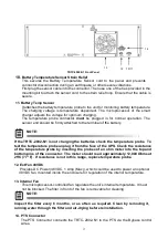
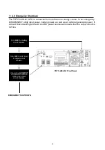
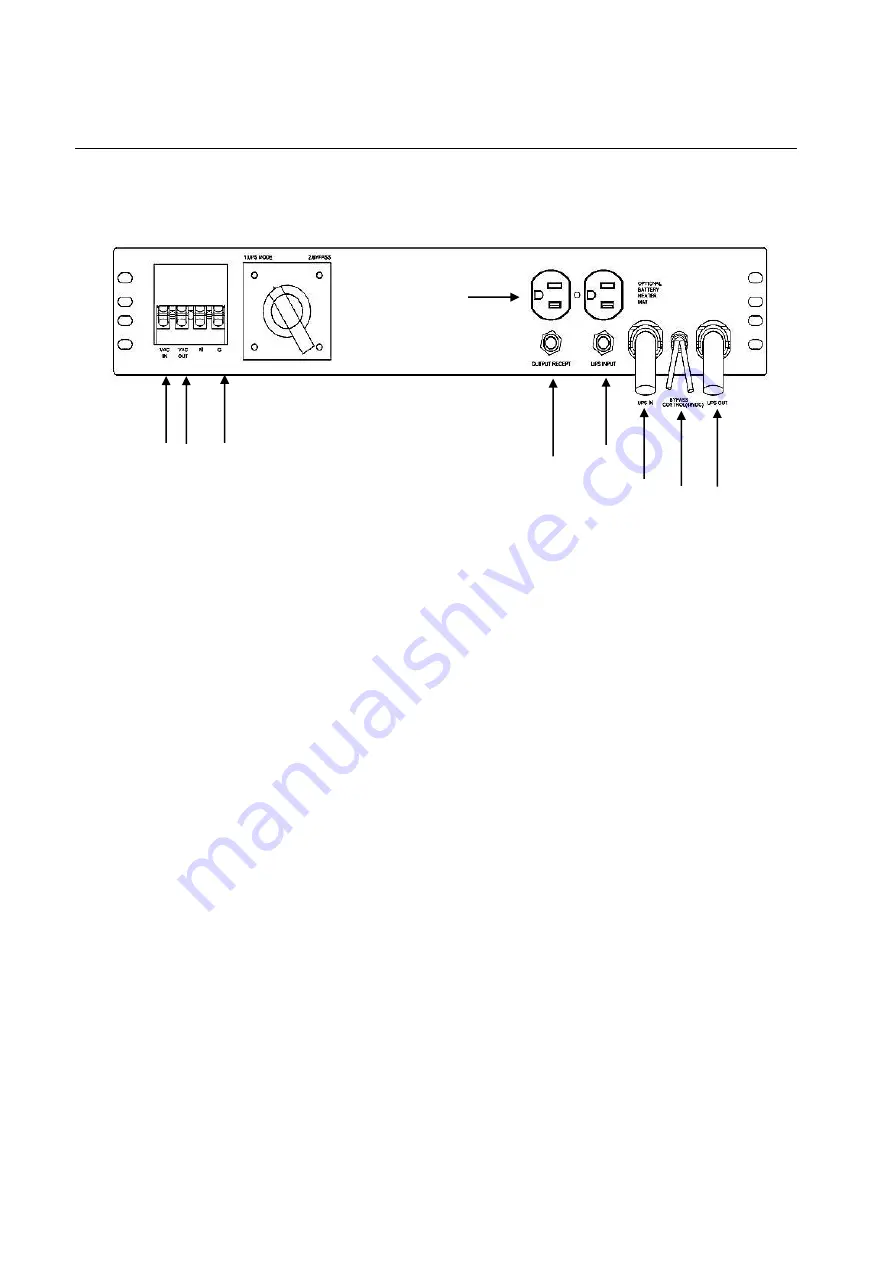
3.2 Power Transfer Switch
The Power Transfer Switch (PTS) shown below allows the UPS to be removed for service,
replacement or maintenance without interrupting power to the traffic cabinet.
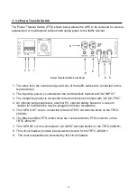
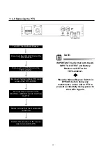
Power Transfer Switch Front Panel
1. The wires from the neutral and ground bus of the traffic cabinet are connected to this
terminal block.
2. The Input line power is connected to the terminal block marked with “AC INPUT”.
3. The Output line power is connected to the terminal block marked with “AC OUTPUT”.
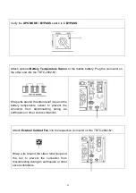
4. An optional surge suppressor, external PC, optional battery heater or a vacuum
cleaner for maintenance may be plugged into these receptacles.
5. This “UPS OUT” cord is connected to the OUTPUT AC terminal block on the TRTC-
2002-N1.
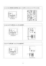
6. The Black and Red PTS control wires are connected to the PTS connector on the
TRTC-2002-N1.
7. This “UPS IN” cord is connected to AC INPUT terminal blocks on the TRTC-2002-N1.
8. This circuit breaker provides input power protection for the TRTC-2002-N1.
9. The dual receptacles are protected by this circuit breaker.
4
2 3 1
5
6
7
8
9
18
Summary of Contents for TRTC-2002-N1
Page 1: ......
Page 2: ...2...
Page 45: ...6 2 Menu Tree 45...
Page 46: ...46...
Page 47: ...47...
Page 48: ...48...
Page 76: ...HyperTerminal at a Glance 76...
Page 87: ......
Page 88: ......
Page 89: ......
Page 90: ......
Page 91: ......
Page 92: ...2017 Marathon Power Inc TRTC 2002 N1 User Manual_Jan_2017 2017 Marathon Power Inc...


