Marantz SR3053 User Manual Download Page 18

NAMES AND 

FUNCTIONS

17

BASIC 

CONNECTIONS

BASIC 

OPERA

TION

ADV

ANCED

CONNECTIONS

SETUP

ADV

ANCED

OPERA

TION

TROUBLESHOOTING

OTHERS

SETUP

SETUP

SPK LEVEL

Here you will set the volume for each speaker so 
that they are all heard by the listener at the same 
level. 


1.

 Select 

SPK LEVEL

 in SETUP MENU with 

3


or 

4

 cursor button, and press the 

ENTER


button.


2.

  To select desired channel, press the 

1

 or 

2


cursor buttons.


3.

 Using 

the 

3

 or 

4

 cursor buttons, adjust the 

volume level of each channel.


4.

  After you complete this portion of the set 

up, press the 

EXIT

 button.

SPK SIZE

Here, set the unit to the size of the speakers you 
have. 


1.

  Select “SPK SIZE” in SETUP MENU with 

3


or 

4

 cursor button, and press the 

ENTER


button.

When setting the speaker size in the SPK SIZE sub-
menu, use the guidelines given below.

LRG:

The complete frequency range for the channel you 
are setting will be output from the speaker.

SML:

Frequencies of the channel you are setting lower 
than approx. 100 Hz will be output from the 
subwoofer.
If the Subwoofer is set to “

NONE

”, the setting of 

the front speakers will be fi xed to “

LRG

,” and the 

sound will be output from both the left and right 
speakers.


2.

  To select the each speaker, press the 

1

 or 

2


cursor buttons.


3.

  To select the setting of each speaker size, 

press the 

3

 or 

4

 cursor buttons.


4.

  After you complete this portion of the set 

up, press the 

EXIT

 button.

FRNT

LRG: 

Select if the front speakers are large.

SML: 

Select if the front speakers are small.

CNTR

LRG:

Select if the center speaker is large.

SML:

Select if the center speaker is small.

NONE:

Select if no center speaker is connected.

SURR

LRG:

Select if the surround left and right speakers are 
large.

SML:

Select if the surround left and right speakers are 
small.

NONE:

Select if no surround left and right speakers are 
connected.

SUB

YES:

Select when a subwoofer is connected.

NONE:

Select when a subwoofer is not connected.

If the front speakers are set to “

SML

”, the setting 

of the subwoofer will be set to “

YES

”.

SPK DIST

Use this parameter to specify the distance of each 
speaker’s position from the listening position. The 
delay time is automatically calculated according to 
these distances.
Begin by determining the ideal or most commonly 
used seating position in the room.
This is important for the timing of the acoustics to 
create the proper sound space that the unit and 
today’s sound systems are able to produce. 

Note

For speakers that you have selected “

NONE

” the 

Speaker Con

fi

 guration sub-menu will not appear 

here. 


1.

 Select 

SPK DIST

 in SETUP MENU with 

3


or 

4

 cursor button, and press the 

ENTER


button.


2.

  To select each speaker , press the 

1

 or 

2


cursor buttons.


3.

  To set the distance for each speaker , press 

the 

3

 or 

4

 cursor buttons.


4.

  After you complete this portion of the set 

up, press the 

ENTER

 button.

FRONT:

Set the distance from the front left and right 
speakers to your normal listening position.

CENTER:

Set the distance from the center speaker to your 
normal listening position.

SURR.:

Set the distance from the surround left and right 
speakers to your normal listening position.

SUB W:

Set the distance from the subwoofer to your normal 
listening position.

Note

• Set the distance to each speaker in meters (m) or 

feet (ft) as follows.

m: 0.3 - 9 m in 0.3 m steps
ft: 1 - 30 ft in 0.1 ft steps
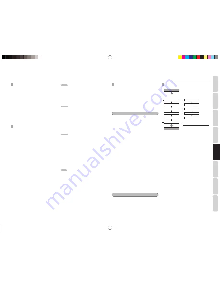
TEST TONE

〉〉〉

FL

Maximum

+10dB

+9dB

0dB

-9dB

-10dB

1dB interval

1dB interval

Minimum

〉〉

CT

〈〈

FR

〈〈〈

SR

〈〈

〉〉

SW

〈〈

〉〉

SL

Press T.TONE button on the 
remote controller.

Automatically change 

the channel

3

/

4

 button

T.TONE

Press T.TONE button to exit 
from Test Tone mode.

T.TONE


1.

 Press 

the 

T.TONE

 button on the remote 

controller.


2.

  The test tone will be cycled through in a 

circular pattern which is FL 

 CT 

 FR 


SR 

 SW 

 SL 

 FL 

 .. increments of 5 

seconds for each channel.

  Using 

the 

3

 or 

4

 cursor buttons, adjust 

the volume level of the noise from the 
speaker so that it is the same level for all 
the speakers. 


3.

  After you complete this portion of the set 

up, press the 

T.TONE

 button.

SR3053̲S̲01̲ENG.indd   17

SR3053̲S̲01̲ENG.indd   17

09.4.21   11:46:54 AM

09.4.21   11:46:54 AM

Summary of Contents for SR3053

Page 1: ...AV Surround Receiver SR3053 SR3053 S 00 cover indd 3 SR3053 S 00 cover indd 3 09 4 21 11 46 21 AM 09 4 21 11 46 21 AM...

Page 2: ...erence ACCESSORIES CHECK Before use check the below accessories were included in the package Remote controller 1 AAA size batteries 2 Power supply cord 1 AM loop antenna 1 FM antenna 1 User guide 1 WA...

Page 3: ...to all of the operating functions and can be used for system operation as well Dolby Digital Dolby Pro Logic II Movie Music Dolby Virtual Speaker Ref wide DTS Digital Surround SOURCE DIRECT Mode Hall...

Page 4: ...ore using batteries Insert the batteries while ensuring that their and poles are properly aligned with the corresponding markings on the remote controller Batteries of the same size and shape may have...

Page 5: ...ode is automatically switched to AUTO when the source direct function is turned on Additionally speakers for which a SMALL speakerconfigurationischosenwillbeautomatically changed to LARGE y DISPLAY bu...

Page 6: ...channel L and R will be illuminated k MUTE indicator This indicator is illuminated when the MUTE is active l kHz MHz indicators These indicators are illuminated when the TUNER FM or AM are active 0 AN...

Page 7: ...ed to cancel setting in the setup menu 4 CONTROL buttons These buttons are used when operating PLAY STOP PAUSE and other commands of a source When TUNER mode is selected BAND button This button is use...

Page 8: ...hich are linked to video outputs The audio jacks are nominally labeled for cassette tape decks compact disc players DVD players and etc The audio inputs and outputs require RCA type connectors e VIDEO...

Page 9: ...HE SPEAKER UNITS FRONT LEFT AND RIGHT SPEAKERS AND A CENTER SPEAKER Align the tweeters and mid range drivers on the three front speakers at the same height as best as possible Note Use magnetically sh...

Page 10: ...Analog Audio OUT IN only Notes Do not connect this unit and other components to mains power until all connections between components have been completed Insert all plugs and connectors securely Incomp...

Page 11: ...n this unit MODEL NO SR3053 MODEL NO SR3053 AC IN AC IN FM FM 75 75 GND GND AM AM ANTENNA ANTENNA DVD DVD L L SL SL C C R R L L R R L L SUB SUB WOOFER WOOFER R R SR SR 5 1CH INPUT 5 1CH INPUT PRE OUT...

Page 12: ...the sound of HDMI audio is not output from the speaker as this unit When output the sound from the Blu ray and DVD sources that connects HDMI cable with this unit a separate audio cable coax digital...

Page 13: ...his unit is not for safety grounding CONNECTING OF AC POWER CABLE 1 Plug the supplied AC power cable to the AC IN socket on the rear panel of the main unit AC IN 2 Plug the power cable into an AC outl...

Page 14: ...interrupt the output to all speakers and the head phone jack but it will not affect any recording or dubbing that may be in progress When the system is muted the display will show MUTE Press the MUTE...

Page 15: ...ol of high frequency sound BASS Adjusts the tone control of low frequency sound DISPLAY Changes the front display mode SLEEP Sets the sleep timer function SIZE Calls up SPK SIZE adjust DISTANCE Calls...

Page 16: ...IGITAL AUDIO IN DIGITAL AUDIO IN IN IN COMPONENT VIDEO COMPONENT VIDEO MONITOR MONITOR OUT OUT P PB B C CB B P PR R C CR R SPEAKER SYSTEMS 6 8 OHMS SPEAKER SYSTEMS 6 8 OHMS CENTER CENTER BLU RAY BLU R...

Page 17: ...e 3 or 4 cursor buttons and press the ENTER button to enter The display will change to the selected sub menu You can move the each sub menu with the 1 or 2 buttons 4 If you desire to exit from this me...

Page 18: ...ont speakers are set to SML the setting of the subwoofer will be set to YES SPK DIST Use this parameter to specify the distance of each speaker s position from the listening position The delay time is...

Page 19: ...ction 5 1CH IN 3 4 button 1 2 button 3 4 button SPK LEVEL LEVEL PANO Select the Panorama mode ON or OFF with the 3 or 4 cursor buttons Panorama wraps the sound of the front left and right speakers aro...

Page 20: ...e signal is output to the TAPE OUT VCR OUT outputs for recording 3 Start recording to the recording component as desired RECORDING THE VIDEO FROM ONE SOURCE AND THE AUDIO FROM ANOTHER You can add the...

Page 21: ...can hear the same sound level from each speaker at the listening position For the front left front right center surround left surround right speakers the output levels can be adjusted between 10 to 10...

Page 22: ...play and then the preset station with the lowest preset number is recalled rst 2 Preset stations are recalled in sequence No 1 No 2 etc for 5 seconds each No stored preset number will be skipped ADVAN...

Page 23: ...AMP function enabled 0 9 Inputs the numeric A D AMP function enabled NIGHT AMP function enabled SURROUND AMP function enabled AUTO AMP function enabled STEREO AMP function enabled S DIRECT AMP functio...

Page 24: ...g speakers with lower impedance than required Always use speakers with the required impedance 28 The unit was placed and used on a narrow rack or similar confined space and became overheated inside Fo...

Page 25: ...YES SUB YES 17 16 17 The playback source does not contain any sound in the low range Night mode does not function Only applies to units with Night mode A source that is not recorded in Dolby Digital...

Page 26: ...cannot play back audio without a digital connection Connect to the source component Blu Ray disc player DVD player by digital connection COAX 11 Image and audio are unstable over an HDMI connection Th...

Page 27: ...SL SR SW DTS 96 24 DTS 5 1 dts L R C SL SR SW DTS 5 1ch DTS 5 1 dts L R C SL SR SW DTS 2ch DTS 2 0 dts L R DTS 1ch DTS 1 0 dts C PCM Audio PCM Stereo PCM L R PCM 96KHz PCM 96KHz Stereo PCM L R HDCD P...

Page 28: ...encoded stereo movie sound tracks Pro Logic II MUSIC This mode provides 5 1 channel surround sound from conventional stereo sources analog or digital such as CD tape FM TV stereo VCR etc Pro Logic Thi...

Page 29: ...etter spatiality and directionality on Dolby Surround program material provides a convincing three dimensional soundfield on conventional stereo music recordings and is ideally suited to bring the sur...

Page 30: ...l substances If the equipment get dirty wipe the external surfaces with a soft lint free cloth If the equipment becomes heavily soiled dilute some washing up liquid in water in a ratio of one part det...

Page 31: ...ind your nearest authorized distributor or dealer on our website is a registered trademark Printed in China 04 2009 541110281047M mzh d SR3053 S 00 cover indd 2 SR3053 S 00 cover indd 2 09 4 21 11 46...

Reviews: