2 - 30
18 - STEERING SELECTION
Before selecting one of the three possible steering positions, bring the 4 wheels into
alignment, i.e., in the straight ahead position.
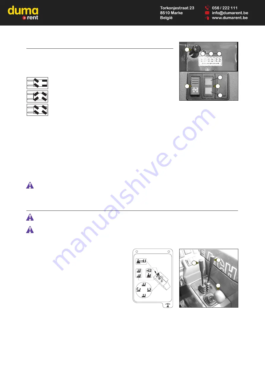
A - STEERING SELECTION LEVER
A1 - Front wheel steer (highway traffic).
A2 - Front and rear wheels steer in opposite direction (4 wheel steer).
A3 - Front and rear wheels steer in the same direction (crab steer).
B - GREEN LAMPS FOR ALIGNMENT OF THE WHEELS
These lamps come on to indicate the alignment of the wheels, in relation to the axle of the lift truck. The lamp B1 for the front
wheels and the lamp B2 for the rear wheels.
C - SWITCH FOR ALIGNMENT OF THE WHEELS
This switch enables the use or not of the device for alignment of the wheels.The indicator light indicates its use.
WHEEL ALIGNMENT PROCEDURE
- Connect the switch (signal light ON).
- Shift the distributor control lever for steering selection A in position A2 (4 wheel steering).
- Turn the steering wheel and bring the rear wheels into alignment until the lamp B2 is on.
- Shift the distributor control lever for steering selection A in position A1 (highway traffic).
- Turn the steering wheel and bring the front wheels into alignment until the lamp B1 is on.
Before driving on roads, it is necessary to check the alignment of the rear wheels and to drive in front wheel steer. The control of the
alignment of the rear wheels must be regularly done with the help of the green lamps, while driving the lift truck. In case of anomalies,
consult your dealer.
19 - HYDRAULIC CONTROLS
Do not attempt to alter the hydraulic system pressure by interfering with the pressure regulating valve. In the event of suspected
malfunction, contact your dealer. ANY ALTERATION MAY RENDER THE WARRANTY NULL AND VOID.
Use the hydraulic controls carefully without jerking, to avoid accidents caused by shaking the lift truck.
MT 523 Série B-E2
MLT 523 Turbo Série B-E2
MT 620 Série B-E2
LIFTING OF THE LOAD
- The lever A backwards when lifting.
- The lever A for wards when lowering.
TILT OF THE CARRIAGE
- The lever A to the left for reverse tilt.
- The lever A to the right for for ward tilt.
TELESCOPING
- The lever B for wards for the extension.
- The lever B backwards for the retraction.
ATTACHMENT
- The lever C for wards or backwards.
B2
B1
A
A3
A1
A2
B
C
B
C
A
N°23
76
1
6
Summary of Contents for B-E2 Series
Page 2: ......
Page 4: ......
Page 5: ...1 1 1 OPERATING AND SAFETY INSTRUCTIONS...
Page 6: ...1 2...
Page 30: ...1 26...
Page 31: ...2 1 2 DESCRIPTION 2 DESCRIPTION...
Page 32: ...2 2...
Page 47: ...2 17...
Page 65: ...2 35...
Page 75: ...3 1 3 MAINTENANCE 3 MAINTENANCE...
Page 76: ...3 2...
Page 78: ...3 4...
Page 97: ...3 23...
Page 103: ...3 29...
Page 107: ...3 33...
Page 109: ...3 35...
Page 116: ...4 2...
Page 118: ...4 4...
Page 127: ...4 13...


