3 - 39
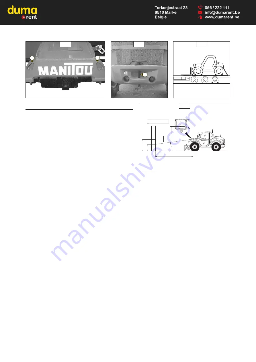
G6 - FRONT HEADLAMPS
ADJUST
RECOMMENDED SETTING
(as per standard ECE-76/756 76/761 ECE20)
Set to - 2% of the dipped beam in relation to the horizontal line of the
headlamp.
ADJUSTING PROCEDURE
- Place the lift truck unloaded and in the transpor t position and
perpendicular to a white wall on flat, level ground (fig. G6).
- Check the tyre pressures (see: 2 - DESCRIPTION: CHARACTERISTICS).
- Put the gear reverser lever in neutral and release the parking brake.
CALCULATING THE HEIGHT OF THE DIPPED BEAM (H2)
• h1
= Height of the dipped beam in relation to the
ground.
• h2
= Height of the adjusted beam.
• l
= Distance between the dipped beam and the white wall.
POUR FACILIT
ER
POUR FACILIT
ER
L'ACCOUPLEMEN
T HYDRAULIQUE,
L'ACCOUPLEMEN
T HYDRAULIQUE,
DECOMPRIMER
LE CIRCUIT,
DECOMPRIMER
LE CIRCUIT,
MOTEUR A L'AR
RET
MOTEUR A L'AR
RET
MADE IN FRANCE
h1
+%
-%
l
h1
h2
-2%
h2 = h1 - (l x 2 / 100)
G6
G5/5
G5/4
G4/2
Summary of Contents for B-E2 Series
Page 2: ......
Page 4: ......
Page 5: ...1 1 1 OPERATING AND SAFETY INSTRUCTIONS...
Page 6: ...1 2...
Page 30: ...1 26...
Page 31: ...2 1 2 DESCRIPTION 2 DESCRIPTION...
Page 32: ...2 2...
Page 47: ...2 17...
Page 65: ...2 35...
Page 75: ...3 1 3 MAINTENANCE 3 MAINTENANCE...
Page 76: ...3 2...
Page 78: ...3 4...
Page 97: ...3 23...
Page 103: ...3 29...
Page 107: ...3 33...
Page 109: ...3 35...
Page 116: ...4 2...
Page 118: ...4 4...
Page 127: ...4 13...


