Omni/Uni Flash Operation
M&R Printing Equipment, Inc. - Glen Ellyn, Illinois
23
AUTO FLASH MODE -
(See page 43 for control instructions)
When using any print station for Auto Flash Operation, the
control panel switches for that particular print station must be
set for the “Front” stop position, and the print station stroke
switch set in the “Single” position. More than one print station
can be activated for flash mode simply by positioning the
switches as described above. Once placed in the auto flash
mode, the print stations will cycle in the auto flash mode and
remain in the auto flash mode as long as the indexer is run-
ning, either manually or in the automatic mode. When the
indexer stops and the dwell time expires, the flash will return
to a standby position (which will be away from the pallet). To
return the print stations to normal print mode, simply flip the
carriage stop toggle switch to the “Rear” stop position.
MANUAL FLASH MODE -
To flash a sample manually or test print, proceed as follows:
1. Position front-rear switch to “Rear” position on the print
station with the Omni Flash.
2. Position single-double switch to either “Single” or
“Double” position.
3. Press the green “Reset” button and the Omni Flash will
move into position over the pallet.
4. Return the single-double switch to the middle position
and the front-rear switch to the front position.
5. Press any print button to raise the carousel to print
position.
6. After flash time is completed, return the single-double
switch to single position and press the reset button to
remove the Omni Flash from over the pallet.
INSTRUCTIONS FOR OMNI/UNI FLASH INSTALLATION:
The following information describes the proper procedure
for the installation of the M&R Omni/Uni Flash cure unit on
M&R Challenger Series II textile screen printing systems.
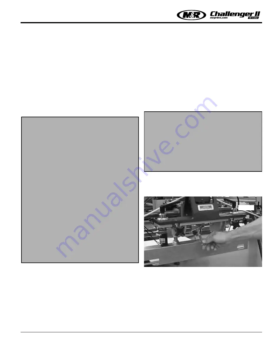
1. After determining the location of the M&R Omni/Uni Flash
Unit, generally print station number “2” in the print
sequence, disengage the latch clamp located on the flip-up
front screen frame holder assembly (See Fig. 1).
2. After loosening the latch clamp as described in number 1
above, lift the entire front screen frame holder assembly up
into the fully raised, vertical position. The flip-up front
screen frame holder assembly should lock into the fully
raised position. (See Fig. 2 top left next page) In the event
the flip-up front screen frame holder assembly does not lock
securely into position, examine the lock assembly for prop-
er operation or contact our Equipment Service Department
at 1 (800) 483-8765 for further assistance.
NOTE:
All Challenger Series II systems can be
retrofitted to accept the Omni Flash or
Quartz Flash Unit.
*
D
ISCLOSURE STATEMENT
: The following parts list
may not all apply to your
Omni Flash Unit, check
with the factory for fur-
ther information.
List of parts:
No. of Items:
Description of Item:
2 Cross knob 1/2 - 20
4 Flat Washer 1/2”
2 Hex nut 1/2” - 20
4 Flat Soc. Cap-Screw 10-24
2 Bolt 3/8” - 16 x 1” lg.
2 Hex nut 3/8” - 16
1 Clamp Bracket
1 Flat Mounting Bracket
1 Flash Adapter Series I to II
1 Flash Hanger
2 Squeegee Clamp (Manual)
NOTE:
The M&R Omni/Uni Flash requires the instal-
lation of electrical power for operation.
Please refer to the Manufacturer’s Rating
Plate located on the side of the control panel
enclosure for the proper electrical specifica-
tions to operate this equipment.
M&R Printing Equipment, Inc. encourages
the use of a professionally licensed electrical
contractor for the installation/connection of
electrical power/service to this equipment.
Fig. 1
Summary of Contents for 12 COLOR
Page 4: ......
Page 6: ......
Page 8: ......
Page 18: ...M R Printing Equipment Inc Glen Ellyn Illinois 10 Specifications NOTES...
Page 38: ...Quartz Flash Operation M R Printing Equipment Inc Glen Ellyn Illinois NOTES 30...
Page 72: ...081200MS PREVENTIVE MAINTENANCE PROCEDURE CHALLENGER Series II NOTES 64...
Page 84: ...PREVENTIVE MAINTENANCE PROCEDURE CHALLENGER Series II NOTES 081200MS 76...
Page 88: ...081200MS PREVENTIVE MAINTENANCE PROCEDURE CHALLENGER Series II NOTES 80...
Page 104: ...PREVENTIVE MAINTENANCE PROCEDURE CHALLENGER Series II NOTES 96...
Page 112: ...PREVENTIVE MAINTENANCE PROCEDURE CHALLENGER Series II NOTES 104...
Page 114: ...081200MS PREVENTIVE MAINTENANCE PROCEDURE CHALLENGER Series II NOTES 106...
Page 116: ...PREVENTIVE MAINTENANCE PROCEDURE CHALLENGER Series II NOTES 108...
Page 118: ...081200MS 110 This page left blank intentionally...
Page 122: ...Leveling the Pallets M R Printing Equipment Inc Glen Ellyn Illinois 114 NOTES...
Page 128: ...Idec Relay Identification NOTES 120...
Page 144: ...Trouble Shooting Procedure NOTES 136...
Page 153: ......
Page 154: ......
Page 156: ......
Page 160: ......
Page 162: ......
Page 164: ......
Page 166: ......
Page 168: ......
Page 172: ......
Page 174: ......
Page 176: ......
Page 178: ......
Page 180: ......
Page 182: ......
Page 184: ......
Page 186: ......
Page 188: ......
Page 190: ......
Page 192: ......
Page 194: ......
Page 196: ......
Page 198: ......
Page 200: ......
Page 202: ......
Page 204: ......
Page 206: ......
Page 208: ......
Page 210: ......
Page 212: ......
Page 214: ......
Page 216: ......
Page 218: ......
Page 220: ......
Page 222: ......
Page 224: ......
Page 228: ......
Page 230: ......
Page 232: ......
Page 234: ......
Page 240: ......


