MAN B&W
6.04
Page 11 of 12
MAN Diesel
MAN B&W L35MC6-TII
198 72 49-0.0
Calculation of Exhaust Data for Derated Engine
Example 3:
Expected exhaust gas data
for a derated 6L35MC6-TII with conventionel MAN Diesel turbocharger type
TCR and fixed pitch propeller.
Based on the engine ratings below, and by means of an example, this chapter will show how to calculate
the expected exhaust gas amount and temperature at service rating, and for a given ambient reference
condition different from ISO.
The calculation is made for the service rating (S) being 80% of the specified MCR power of the diesel engine.
Nominal MCR, (L
1
)
P
L1
: 3,900 kW (100.0%) and 210.0 r/min (100.0%)
Specified MCR, (M)
P
M
: 3,315 kW (85.0%) and 189.0 r/min (90.0%)
Optmising point, (O) P
O
: 3,315 kW (85.0%) and 189.0 r/min (90.0%), P
O
= 100.0% of P
M
Service rating, (S)
P
S
: 2,652 kW and 175.5 r/min, P
S
= 80.0% of P
M
Reference conditions
Air temperature T
air
........................................ 20 °C
Scavenge air coolant temperature T
CW
......... 18 °C
Barometric pressure p
bar
....................... 1,013 mbar
Exhaust gas backpressure
at specified MCR
∆
p
M
.........................300 mm WC
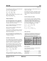
a) Correction for choice of specified MCR point M
and optmising point O:
P
M%
=
3,315
____
3,900
x 100 = 85.0%
n
M%
=
189.0
____
210.0
x 100 = 90.0%
By means of Figs. 6.04.07 and 6.04.08:
∆
m
M%
= + 0.25%
∆
T
M
= 7.2 °C
As the engine is optmised in O lower than 100% M,
and P
O%
= 100.0% of P
M
we get by means of equation [6]
∆
T
O
= 0.3 x (100 100.0) = 0.0 °C
b) Correction for ambient conditions and
backpressure:
By means of equations [7] and [8]:
∆
M
amb%
= 0.41 x (20 25) + 0.03 x (1,013 1,000)
+ 0.19 x (18 25) 0.011 x (300 300)%
∆
M
amb%
= + 1.11%
∆
T
amb
= 1.6 x (20 25) 0.01 x (1,013 1,000)
+ 0.1 x (18 25) + 0.05 x (300 300) °C
∆
T
amb
= 8.8 °C
c) Correction for the engine load:
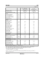
Service rating = 80% of specified MCR power
By means of Figs. 6.04.11 and 6.04.12:
∆
m
S%
= + 7.1%
∆
T
S
= 18.8 °C
Summary of Contents for B&W L35MC6-TII
Page 4: ......
Page 10: ......
Page 18: ......
Page 19: ...MAN B W MAN Diesel Engine Design 1 ...
Page 20: ......
Page 35: ...MAN B W MAN Diesel Engine Layout and Load Diagrams SFOC 2 ...
Page 36: ......
Page 52: ......
Page 64: ......
Page 65: ...MAN B W MAN Diesel Turbocharger Selection Exhaust Gas By pass 3 ...
Page 66: ......
Page 72: ......
Page 73: ...MAN B W MAN Diesel Electricity Production 4 ...
Page 74: ......
Page 95: ...MAN B W MAN Diesel Installation Aspects 5 ...
Page 96: ......
Page 132: ......
Page 146: ......
Page 147: ...MAN B W MAN Diesel List of Capacities Pumps Coolers Exhaust Gas 6 ...
Page 148: ......
Page 171: ...MAN B W MAN Diesel Fuel 7 ...
Page 172: ......
Page 186: ......
Page 187: ...MAN B W MAN Diesel Lubricating Oil 8 ...
Page 188: ......
Page 203: ...MAN B W MAN Diesel Cylinder Lubrication 9 ...
Page 204: ......
Page 213: ...MAN B W MAN Diesel Piston Rod Stuffing Box Drain Oil 10 ...
Page 214: ......
Page 215: ......
Page 217: ...MAN B W MAN Diesel Central Cooling Water System 11 ...
Page 218: ......
Page 223: ...MAN B W MAN Diesel Seawater Cooling System 12 ...
Page 224: ......
Page 234: ......
Page 235: ...MAN B W MAN Diesel Starting and Control Air 13 ...
Page 236: ......
Page 242: ......
Page 243: ...MAN B W MAN Diesel Scavenge Air 14 ...
Page 244: ......
Page 256: ......
Page 257: ...MAN B W MAN Diesel Exhaust Gas 15 ...
Page 258: ......
Page 272: ......
Page 273: ...MAN B W MAN Diesel Engine Control System 16 ...
Page 274: ......
Page 289: ...MAN B W MAN Diesel Vibration Aspects 17 ...
Page 290: ......
Page 304: ......
Page 305: ...MAN B W MAN Diesel Monitoring Systems and Instrumentation 18 ...
Page 306: ......
Page 328: ......
Page 329: ...MAN B W MAN Diesel Dispatch Pattern Testing Spares and Tools 19 ...
Page 330: ......
Page 360: ......
Page 361: ...MAN B W MAN Diesel Project Suppport and Documentation 20 ...
Page 362: ......
Page 371: ...MAN B W MAN Diesel Appendix A ...
Page 372: ......

