


MAN B&W
8.05
Page 2 of 3
MAN Diesel
MAN B&W S46MC-C, S46ME-B, S42MC, S40MC-C,S40ME-B,
S35MC, S35MC-C, S35ME-B, L35MC, S26MC
198 59 104.2
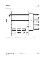
Lubricating oil full flow filter
Lubricating oil flow .............. see ‘List of capacities’
Working pressure .........................................4.0 bar
Test pressure .....................according to class rules
Absolute fineness .........................................40
µ
m*
Working temperature ............. approximately 45 °C
Oil viscosity at working temp. ............. 90 100 cSt
Pressure drop with clean filter ....maximum 0.2 bar
Filter to be cleaned
at a pressure drop .......................maximum 0.5 bar
* The absolute fineness corresponds to a nominal
fineness of approximately 25
µ
m at a retaining
rate of 90%.
The flow capacity must be within a range from
100 to 112% of the capacity stated.
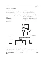
The fullflow filter should be located as close as
possible to the main engine.
If a double filter (duplex) is installed, it should
have sufficient capacity to allow the specified full
amount of oil to flow through each side of the filter
at a given working temperature with a pressure
drop across the filter of maximum 0.2 bar (clean
filter).
If a filter with a backflushing arrangement is in-
stalled, the following should be noted:
• The required oil flow, specified in the ‘List of
capacities’, should be increased by the amount
of oil used for the backflushing, so that the
lubricating oil pressure at the inlet to the main
engine can be maintained during cleaning.
• If an automatically cleaned filter is installed, it
should be noted that in order to activate the
cleaning process, certain makes of filter require
a higher oil pressure at the inlet to the filter than
the pump pressure specified. Therefore, the
pump capacity should be adequate for this pur-
pose, too.
Flushing of lube oil system
Before starting the engine for the first time, the lu-
bricating oil system on board has to be cleaned in
accordance with MAN Diesel’s recommendations:
‘Flushing of Main Lubricating Oil System’, which is
available on request.
Summary of Contents for B&W L35MC6-TII
Page 4: ......
Page 10: ......
Page 18: ......
Page 19: ...MAN B W MAN Diesel Engine Design 1 ...
Page 20: ......
Page 35: ...MAN B W MAN Diesel Engine Layout and Load Diagrams SFOC 2 ...
Page 36: ......
Page 52: ......
Page 64: ......
Page 65: ...MAN B W MAN Diesel Turbocharger Selection Exhaust Gas By pass 3 ...
Page 66: ......
Page 72: ......
Page 73: ...MAN B W MAN Diesel Electricity Production 4 ...
Page 74: ......
Page 95: ...MAN B W MAN Diesel Installation Aspects 5 ...
Page 96: ......
Page 132: ......
Page 146: ......
Page 147: ...MAN B W MAN Diesel List of Capacities Pumps Coolers Exhaust Gas 6 ...
Page 148: ......
Page 171: ...MAN B W MAN Diesel Fuel 7 ...
Page 172: ......
Page 186: ......
Page 187: ...MAN B W MAN Diesel Lubricating Oil 8 ...
Page 188: ......
Page 203: ...MAN B W MAN Diesel Cylinder Lubrication 9 ...
Page 204: ......
Page 213: ...MAN B W MAN Diesel Piston Rod Stuffing Box Drain Oil 10 ...
Page 214: ......
Page 215: ......
Page 217: ...MAN B W MAN Diesel Central Cooling Water System 11 ...
Page 218: ......
Page 223: ...MAN B W MAN Diesel Seawater Cooling System 12 ...
Page 224: ......
Page 234: ......
Page 235: ...MAN B W MAN Diesel Starting and Control Air 13 ...
Page 236: ......
Page 242: ......
Page 243: ...MAN B W MAN Diesel Scavenge Air 14 ...
Page 244: ......
Page 256: ......
Page 257: ...MAN B W MAN Diesel Exhaust Gas 15 ...
Page 258: ......
Page 272: ......
Page 273: ...MAN B W MAN Diesel Engine Control System 16 ...
Page 274: ......
Page 289: ...MAN B W MAN Diesel Vibration Aspects 17 ...
Page 290: ......
Page 304: ......
Page 305: ...MAN B W MAN Diesel Monitoring Systems and Instrumentation 18 ...
Page 306: ......
Page 328: ......
Page 329: ...MAN B W MAN Diesel Dispatch Pattern Testing Spares and Tools 19 ...
Page 330: ......
Page 360: ......
Page 361: ...MAN B W MAN Diesel Project Suppport and Documentation 20 ...
Page 362: ......
Page 371: ...MAN B W MAN Diesel Appendix A ...
Page 372: ......