MAN Diesel
4.07
Page 3 of 3
MAN Diesel
198 42 066.5
MAN B&W S80MC/MC-C/ME-C, K80MC-C/ME-C, S70MC/MC-C/ME-C/ME-GI,
L70MC-C/ME-C, S65ME-C/ME-GI, S60MC/MC-C/ME-C/ME-GI/ME-B,
L60MC-C/ME-C, S50MC/MC-C/ME-C/ME-B, S46MC-C/ME-B, S42MC,
S40MC-C/ME-B, S35MC/MC-C/ME-B, L35MC, S26MC
L21/31 GenSet Data
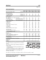
Fig. 4.07.02a: List of capacities for L21/31, 1,000 rpm, IMO Tier I. Tier II values available on request.
Cyl.
5
6
7
8
9
Maximum continuous rating at
1000 rpm
kW
1,000
1,320
1,540
1,760
1,980
Engine-driven pumps:
LT cooling water pump
(1-2.5 bar) m³/h
61
61
61
61
61
HT cooling water pump
(1-2.5 bar) m³/h
61
61
61
61
61
Lubricating oil pump
(3-5 bar) m³/h
34
34
46
46
46
External pumps:
Max. delivery pressure of cooling water pumps
bar
2.5
2.5
2.5
2.5
2.5
Diesel oil pump
(5 bar at fuel oil inlet A1) m³/h
0.69
0.92
1.08
1.23
1.38
Fuel oil supply pump
(4 bar discharge pressure) m³/h
0.34
0.45
0.53
0.60
0.68
Fuel oil circulating pump
(8 bar at fuel oil inlet A1) m³/h
0.70
0.93
1.09
1.25
1.40
Cooling capacities:
Lubricating oil
kW
206
162
192
222
252
LT charge air
kW
125
333
388
443
499
Total LT system
kW
331
495
580
665
751
LT flow at 36°C inlet and 44°C outlet*
m³/h
35.5
47.8
52.1
56.2
60.5
Jacket cooling
kW
163
280
332
383
435
HT charge air
kW
212
361
411
460
509
Total HT system
kW
374
641
743
843
944
HT flow at 44°C inlet and 80°C outlet*
m³/h
8.9
20.9
23.9
26.7
29.5
Total from engine
kW
705
1136
1323
1508
1695
LT flow from engine at 36°C inlet
m³/h
35.5
47.2
51.5
55.6
59.9
LT outlet temperature from engine at 36°C inlet
°C
53
57
59
60
61
(1-string cooling water system)
Gas data:
Exhaust gas flow
kg/h
6,920
10,200
11,900
13,600
15,300
Exhaust gas temperature at turbine outlet
°C
335
333
333
333
333
Maximum allowable back pressure
bar
0.025
0.025
0.025
0.025
0.025
Air consumption
kg/h
6,720
9,940
11,600
13,200
14,900
Starting air system:
Air consumption per start incl. air for jet assist
Nm³
1.0
1.2
1.4
1.6
1.8
Heat radiation:
Engine
kW
21
47
50
54
56
Alternator
kW
( See separate data from alternator maker )
The stated heat balances are based on 100% load and tropical
condition.
The mass flows and exhaust gas temperature are based on ISO
ambient condition.
* The outlet temperature of the HT water is fixed to 80°C, and
44°C for the LT water.
At different inlet temperature the flow will change accordingly.
Example: If the inlet temperature is 25°C then the LT flow will
change to (44-36)/(44-25)*100 = 42% of the original flow.
The HT flow will not change.
17856 53-3.0
Summary of Contents for B&W L35MC6-TII
Page 4: ......
Page 10: ......
Page 18: ......
Page 19: ...MAN B W MAN Diesel Engine Design 1 ...
Page 20: ......
Page 35: ...MAN B W MAN Diesel Engine Layout and Load Diagrams SFOC 2 ...
Page 36: ......
Page 52: ......
Page 64: ......
Page 65: ...MAN B W MAN Diesel Turbocharger Selection Exhaust Gas By pass 3 ...
Page 66: ......
Page 72: ......
Page 73: ...MAN B W MAN Diesel Electricity Production 4 ...
Page 74: ......
Page 95: ...MAN B W MAN Diesel Installation Aspects 5 ...
Page 96: ......
Page 132: ......
Page 146: ......
Page 147: ...MAN B W MAN Diesel List of Capacities Pumps Coolers Exhaust Gas 6 ...
Page 148: ......
Page 171: ...MAN B W MAN Diesel Fuel 7 ...
Page 172: ......
Page 186: ......
Page 187: ...MAN B W MAN Diesel Lubricating Oil 8 ...
Page 188: ......
Page 203: ...MAN B W MAN Diesel Cylinder Lubrication 9 ...
Page 204: ......
Page 213: ...MAN B W MAN Diesel Piston Rod Stuffing Box Drain Oil 10 ...
Page 214: ......
Page 215: ......
Page 217: ...MAN B W MAN Diesel Central Cooling Water System 11 ...
Page 218: ......
Page 223: ...MAN B W MAN Diesel Seawater Cooling System 12 ...
Page 224: ......
Page 234: ......
Page 235: ...MAN B W MAN Diesel Starting and Control Air 13 ...
Page 236: ......
Page 242: ......
Page 243: ...MAN B W MAN Diesel Scavenge Air 14 ...
Page 244: ......
Page 256: ......
Page 257: ...MAN B W MAN Diesel Exhaust Gas 15 ...
Page 258: ......
Page 272: ......
Page 273: ...MAN B W MAN Diesel Engine Control System 16 ...
Page 274: ......
Page 289: ...MAN B W MAN Diesel Vibration Aspects 17 ...
Page 290: ......
Page 304: ......
Page 305: ...MAN B W MAN Diesel Monitoring Systems and Instrumentation 18 ...
Page 306: ......
Page 328: ......
Page 329: ...MAN B W MAN Diesel Dispatch Pattern Testing Spares and Tools 19 ...
Page 330: ......
Page 360: ......
Page 361: ...MAN B W MAN Diesel Project Suppport and Documentation 20 ...
Page 362: ......
Page 371: ...MAN B W MAN Diesel Appendix A ...
Page 372: ......


