


MAN B&W
1.06
Page 1 of 7
MAN Diesel
198 74 728.0
MAN B&W S50MC/MC-C-TII, S46MC-C-TII, S42MC-TII,
S35MC-TII, L35MC-TII, S26MC-TII
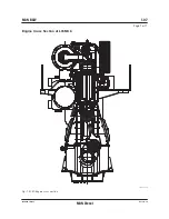
MC Engine Description
Please note that engines built by our licensees
are in accordance with MAN Diesel drawings and
standards but, in certain cases, some local stand-
ards may be applied; however, all spare parts are
interchangeable with MAN Diesel designed parts.
Some components may differ from MAN Diesel’s
design because of local production facilities or
the application of local standard components.
In the following, reference is made to the item
numbers specified in the ‘Extent of Delivery’ (EoD)
forms, both for the ‘Basic’ delivery extent and for
some ‘Options’.
Bedplate and Main Bearing
The bedplate is made with the thrust bearing in
the aft end of the engine. The bedplate consists
of high, welded, longitudinal girders and welded
cross girders with cast steel bearing supports.
For fitting to the engine seating in the ship, long,
elastic holdingdown bolts, and hydraulic tighten-
ing tools are used.
The bedplate is made without taper for engines
mounted on epoxy chocks.
The oil pan, which is made of steel plate and is
welded to the bedplate, collects the return oil from
the forced lubricating and cooling oil system. The
oil outlets from the oil pan are normally vertical
and are provided with gratings.
Horizontal outlets at both ends can be arranged
for some cylinder numbers, however, this must be
confirmed by the engine builder.
The main bearings consist of thin walled steel
shells lined with bearing metal. The main bearing
bottom shell can be rotated out and in by means
of special tools in combination with hydraulic
tools for lifting the crankshaft. The shells are kept
in position by a bearing cap.
Frame Box
The frame box is of triangular plate welded or rib
design. On the exhaust side, it is provided with
relief valves for each cylinder while, on the ma-
noeuvring side, it is provided with a large hinged
door for each cylinder. The crosshead guides are
welded onto the frame box.
The frame box is bolted to the bedplate. The bed-
plate, frame box and cylinder frame are tightened
together by stay bolts.
Cylinder Frame and Stuffing Box
The cylinder frame is either welded or cast and
is provided with access covers for cleaning the
scavenge air space, if required, and for inspec-
tion of scavenge ports and piston rings from the
manoeuvring side. Together with the cylinder
liner, it forms the scavenge air space.
The cylinder frame is fitted with pipes for the
piston cooling oil inlet. The scavenge air receiver,
turbocharger, air cooler box, lubricators and gal-
lery brackets are located on the cylinder frame.
At the bottom of the cylinder frame there is a pis-
ton rod stuffing box, provided with sealing rings
for scavenge air. Oil scraper rings in the stuffing
box prevent crankcase oil from coming up into
the scavenge air space and polluting the crank-
case oil with combustion waste products.
Drains from the scavenge air space and the pis-
ton rod stuffing box are located at the bottom of
the cylinder frame.
Summary of Contents for B&W L35MC6-TII
Page 4: ......
Page 10: ......
Page 18: ......
Page 19: ...MAN B W MAN Diesel Engine Design 1 ...
Page 20: ......
Page 35: ...MAN B W MAN Diesel Engine Layout and Load Diagrams SFOC 2 ...
Page 36: ......
Page 52: ......
Page 64: ......
Page 65: ...MAN B W MAN Diesel Turbocharger Selection Exhaust Gas By pass 3 ...
Page 66: ......
Page 72: ......
Page 73: ...MAN B W MAN Diesel Electricity Production 4 ...
Page 74: ......
Page 95: ...MAN B W MAN Diesel Installation Aspects 5 ...
Page 96: ......
Page 132: ......
Page 146: ......
Page 147: ...MAN B W MAN Diesel List of Capacities Pumps Coolers Exhaust Gas 6 ...
Page 148: ......
Page 171: ...MAN B W MAN Diesel Fuel 7 ...
Page 172: ......
Page 186: ......
Page 187: ...MAN B W MAN Diesel Lubricating Oil 8 ...
Page 188: ......
Page 203: ...MAN B W MAN Diesel Cylinder Lubrication 9 ...
Page 204: ......
Page 213: ...MAN B W MAN Diesel Piston Rod Stuffing Box Drain Oil 10 ...
Page 214: ......
Page 215: ......
Page 217: ...MAN B W MAN Diesel Central Cooling Water System 11 ...
Page 218: ......
Page 223: ...MAN B W MAN Diesel Seawater Cooling System 12 ...
Page 224: ......
Page 234: ......
Page 235: ...MAN B W MAN Diesel Starting and Control Air 13 ...
Page 236: ......
Page 242: ......
Page 243: ...MAN B W MAN Diesel Scavenge Air 14 ...
Page 244: ......
Page 256: ......
Page 257: ...MAN B W MAN Diesel Exhaust Gas 15 ...
Page 258: ......
Page 272: ......
Page 273: ...MAN B W MAN Diesel Engine Control System 16 ...
Page 274: ......
Page 289: ...MAN B W MAN Diesel Vibration Aspects 17 ...
Page 290: ......
Page 304: ......
Page 305: ...MAN B W MAN Diesel Monitoring Systems and Instrumentation 18 ...
Page 306: ......
Page 328: ......
Page 329: ...MAN B W MAN Diesel Dispatch Pattern Testing Spares and Tools 19 ...
Page 330: ......
Page 360: ......
Page 361: ...MAN B W MAN Diesel Project Suppport and Documentation 20 ...
Page 362: ......
Page 371: ...MAN B W MAN Diesel Appendix A ...
Page 372: ......


