


MAN B&W
16.01
Page 3 of 11
MAN Diesel
198 79 06-8.0
MAN B&W S46MC-C, S42MC, S40MC-C,
S/L35MC, S35MC-C, S26MC
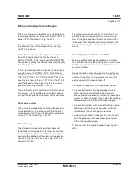
The slow turning valve diverts the starting air to
partially bypass the main starting valve. During
slow turning the engine will rotate so slowly that,
in the event that liquids have accumulated on the
piston top, the engine will stop before any harm
occurs.
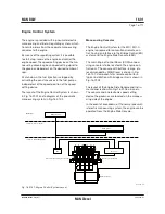
Control System for Plants with CPP
Where a controllable pitch propeller is installed,
the control system is to be designed in such a way
that the operational requirements for the whole
plant are fulfilled.
Special attention should be paid to the actual op-
eration mode, e.g. combinator curve with/without
constant frequency shaft generator or constant
engine speed with a power take off.
The following requirements have to be fulfilled:
• The control system is to be equipped with a
load control function limiting the maximum
torque (fuel pump index) in relation to the engine
speed, in order to prevent the engine from being
loaded beyond the limits of the load diagram
• The control system must ensure that the engine
load does not increase at a quicker rate than
permitted by the scavenge air pressure
• Load changes have to take place in such a way
that the governor can keep the engine speed
within the required range.
Please contact the engine builder to get specific
data.
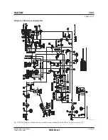
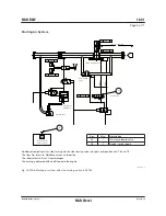
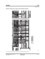
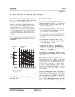
The basic manoeuvring diagram is applicable for
reversible engines, i.e. those with Fixed Pitch Pro-
peller (FPP), and shown in Fig. 16.01.02.
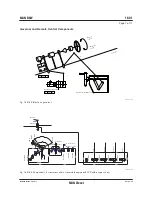
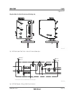
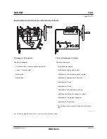
The lever on the Engine Side Console can be set
to either Manual or Remote position, see Fig.
16.01.06a, b and c.
In the Manual position the engine is controlled
from the Engine Side Console by the push
buttons START, STOP, and the AHEAD/ASTERN.
The speed is set by the ‘Manual speed setting’ by
the handwheel.
In the ‘Remote’ position all signals to the engine
are electronic, the START, STOP, AHEAD and
ASTERN signals activate the solenoid valves ZV
1137 C, ZV 1136 C, ZV 1141 C and ZV 1142 C re-
spectively, shown in Figs. 16.01.02 and 16.01.05,
and the speed setting signal via the electronic
governor and the actuator E 1182 C.
The electrical signal comes from the remote con-
trol system, i.e. the Bridge Control (BC) console,
or from the Engine Control Room (ECR) console.
Shut down system
The engine is stopped by activating the puncture
valve located in the fuel pump either at normal
stopping or at shut down by activating solenoid
valve
ZV 1103 C, see Fig. 16.01.02.
Slow turning
The standard manoeuvring system does not
feature slow turning before starting, but for Unat-
tended Machinery Spaces (UMS) we strongly rec-
ommend the addition of the slow turning device
shown in Fig. 16.01.02 as well as Fig. 16.01.03,
option: 4 50 140.
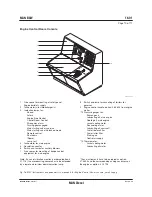
Manoeuvring System on Engine
Summary of Contents for B&W L35MC6-TII
Page 4: ......
Page 10: ......
Page 18: ......
Page 19: ...MAN B W MAN Diesel Engine Design 1 ...
Page 20: ......
Page 35: ...MAN B W MAN Diesel Engine Layout and Load Diagrams SFOC 2 ...
Page 36: ......
Page 52: ......
Page 64: ......
Page 65: ...MAN B W MAN Diesel Turbocharger Selection Exhaust Gas By pass 3 ...
Page 66: ......
Page 72: ......
Page 73: ...MAN B W MAN Diesel Electricity Production 4 ...
Page 74: ......
Page 95: ...MAN B W MAN Diesel Installation Aspects 5 ...
Page 96: ......
Page 132: ......
Page 146: ......
Page 147: ...MAN B W MAN Diesel List of Capacities Pumps Coolers Exhaust Gas 6 ...
Page 148: ......
Page 171: ...MAN B W MAN Diesel Fuel 7 ...
Page 172: ......
Page 186: ......
Page 187: ...MAN B W MAN Diesel Lubricating Oil 8 ...
Page 188: ......
Page 203: ...MAN B W MAN Diesel Cylinder Lubrication 9 ...
Page 204: ......
Page 213: ...MAN B W MAN Diesel Piston Rod Stuffing Box Drain Oil 10 ...
Page 214: ......
Page 215: ......
Page 217: ...MAN B W MAN Diesel Central Cooling Water System 11 ...
Page 218: ......
Page 223: ...MAN B W MAN Diesel Seawater Cooling System 12 ...
Page 224: ......
Page 234: ......
Page 235: ...MAN B W MAN Diesel Starting and Control Air 13 ...
Page 236: ......
Page 242: ......
Page 243: ...MAN B W MAN Diesel Scavenge Air 14 ...
Page 244: ......
Page 256: ......
Page 257: ...MAN B W MAN Diesel Exhaust Gas 15 ...
Page 258: ......
Page 272: ......
Page 273: ...MAN B W MAN Diesel Engine Control System 16 ...
Page 274: ......
Page 289: ...MAN B W MAN Diesel Vibration Aspects 17 ...
Page 290: ......
Page 304: ......
Page 305: ...MAN B W MAN Diesel Monitoring Systems and Instrumentation 18 ...
Page 306: ......
Page 328: ......
Page 329: ...MAN B W MAN Diesel Dispatch Pattern Testing Spares and Tools 19 ...
Page 330: ......
Page 360: ......
Page 361: ...MAN B W MAN Diesel Project Suppport and Documentation 20 ...
Page 362: ......
Page 371: ...MAN B W MAN Diesel Appendix A ...
Page 372: ......


