


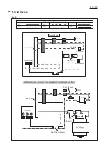
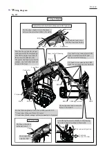

W
iring diagram
P
17
/
18
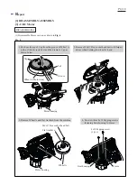
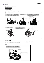
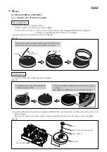
Wiring to DC Motor
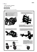
Wiring in Motor Housing R
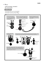
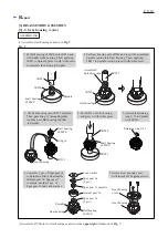
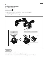
Setting of Controller to Handle L
Motor housing R
DC Motor
Lead wire
holder A
Rib B
DC Motor
Handle L
Controller
Lead wires
Facing the wire connected side to Handle L side,
set Controller to Handle L.
And push Controller until it stops.
And then, make sure that any of its Lead wires
do not cross over the joint line of Handle L’ s edge.
Joint line
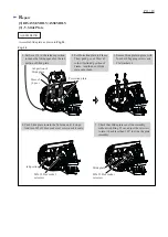
Lead wires (red, blue) have to be put
into Lead wire holders A and B.
Pass the Lead wires through Line filters.
Line filter
Put one Line filter between Rib A
and Lead wire holder A.
And put another one between Rib B
and Lead wire holder A.
Red marking
Fig. D-2
Fig. D-3
Fig. D-4
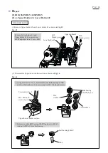
Lead wire (blue) of Controller unit has to be put
under Flag receptacle of Lead wire (red).
Lead wire
holder B
Rib A
Red marking
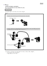
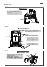
When DC motor is mounted to Housing L,
check the following.
•
Route the Lead wires to Housing L side.
•
Red marking is located as drawn to the right.


