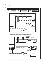
Fuse (if used)
W
iring diagram
P
18
/
18
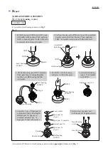
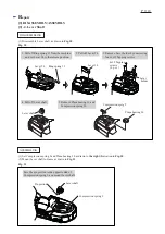
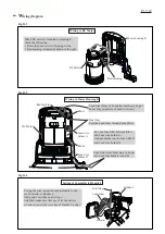
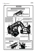
Wiring in Handle
Controller
Line filter
Terminal
Rib A
Rib B
Fig. D-5
Rib C
Rib J
Inner wall of Housing
Rib D
Do not put any lead wires onto
Ribs C, D, E and F.
Fix Lead wires connected to LED
light circuit with Lead wire holders.
Rib E
Rib F
Rib I
Connector
Controller unit’s lead wires (blue, red) with Connector
Inner wall
Rib H
Put the above Lead wires to the place
between Inner wall and Ribs I, H and G.
Rib G
Switch
LED light circuit
Fuse
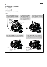
Put Fuse to the place
as drawn below.
Switch
Do not put Fuse
onto this Rib.
Fix the above lead wires
with this lead wire holder.
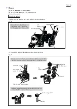
Pass Lead wires (black, orange)
connected to DC Motor through
Line filter and put Line filter to
the room surrounded by ribs.
Except for the Lead wires (balck,
orange), any lead wires must not
be put in the room.
Pass Lead wires connected to LED
light circuit between Rib J and
the inner wall of Housing.
Put the following lead wires between Rib A and Rib B.
* Lead wires (blue, red) from DC motor
* Lead wires (black, orange, yellow) connected to Terminal
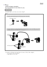
Set LED light circuit to Handle L while facing
the wire connected portion to Front side.
Wire connected portion
Front side
(Lever 54 side)

