S12800 Routing Switch Installa
tion Manual V1.0
Maipu Confidential & Proprietary Information
Page 85
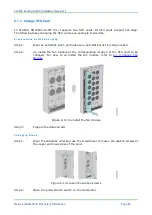
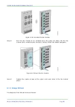
Figure 6-17 Insert the SFU card
Step 7:
Screw on the captive screws at the two sides of the card manually, and then use
the screwdriver to tighten the captive screws and fix the card.
6.1.4 Change Fan Module
Do not touch any uncovering lead, terminal, or dangerous voltage sign part marked on the
product to avoid human injury.
The fan module supports hot plugging. If the fan module is replaced in the switch working
state, do not remove the replaced fan module out of the chassis. Remove the fan module
when the fan stops rotating. Meanwhile, to avoid injury, do not stretch your hand into the
fan module in case of the fan is still running.
Before replacing the fan module, prepare the new fan module in advance. When the fan
module is uninstalled in the switch working state, the new fan module needs to be
installed immediately (it is suggested that the whole changing process does not exceed
2minutes) to ensure normal switch working.
The fan module changing process of S12800 routing switch chassis is similar. The following
takes SM12800-12-MF (V1) as an example to describe how to change the fan module. The
changing steps are as follows:
Step 1:
Wear the antistatic wrist and use the screwdriver to loosen the captive screws at
the upper and lower sides of the fan module.
Step 2:
Use one hand to hold the handle of the fan module and the other hand to hold
the fan chassis of the fan module. Pull out the fan module along the guide rail
smoothly. Place the un-installed fan module on the anti-static mat or in the
initial packing box. The diagram of un-installing the fan module is as follows:


