© 2017 Sensata Technologies
viii
List of Tables
Table 2-1, Wire/Overcurrent Device ........................................16
Table 2-2, Minimum Wire Size to Circuit-breaker Size ................22
Table 2-3, Wire Color to AC Wire Connection ............................22
Table 3-1, Inverter Battery Turn On/Off Levels ..........................36
Table 3-2, Inverter/Charger Default Settings ............................38
Table 4-1, Troubleshooting Guide ............................................40
Table 5-1, MMS Series Speci
fi
cations .......................................42
List of Figures
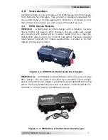
Figure 1-1, MMS1012 Model Inverter/Charger ........................... 1
Figure 1-2, MMS1012-G Model Inverter/Charger ........................ 1
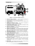
Figure 1-3, Top and Left Side Features ..................................... 4
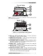
Figure 1-4, Front and Back Side Features .................................. 5
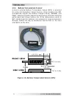
Figure 1-5, Battery Temperature Sensor (BTS) .......................... 6
Figure 2-1, MMS1012 Model Basic Installation Diagram .............. 8
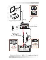
Figure 2-2, MMS1012-G Model Basic Installation Diagram ........... 9
Figure 2-3, Approved MMS1012 (-G) Mounting Orientations ......11
Figure 2-4, MMS1012 Model Dimensions ..................................12
Figure 2-5, MMS1012-G Model Dimensions ..............................13
Figure 2-6, DC Cable to Battery Terminals ................................17
Figure 2-7, DC Cable to Inverter’s DC Terminals .......................18
Figure 2-8, Battery String Connections ....................................20
Figure 2-9, AC Wiring Connections (MMS1012 model) ...............24
Figure 2-10, Neutral-to-Ground Connection (Inverter Mode) .......26
Figure 2-11, Neutral-to-Ground Connection (Standby Mode) .......26
Figure 2-12, Disconnecting Neutral-to-Ground Connection .........27
Figure 2-13, Warning Label ....................................................28
Figure 3-1, Automatic 4-Stage Charging Graph .........................33
Figure 3-2, BTS Temperature to Charge Voltage Change ............34
Figure B-1, Series Battery Wiring ............................................44
Figure B-2, Parallel Battery Wiring ..........................................45
Figure B-3, Series-Parallel Battery Wiring.................................45
Figure B-4, Battery Bank Wiring Examples (12-volt) ..................46
Table of Contents (cont.)
4.3
Resetting the Inverter ..............................................39
4.4 Troubleshooting
......................................................40
5.0 Specifi cations ............................................................42
A-1 Optional Equipment and Accessories .........................43
B-1 Battery
Information
..................................................44
C-1 Warranty/Service
Information
..................................47
C-1.1 Limited
Warranty
....................................................47
C-1.2 How to Receive Repair Service ..................................48
Table of Contents

