© 2017 Sensata Technologies
20
Installation
DC Positive Wire
Mount the DC fuse block and disconnect (or circuit breaker assembly)
as near as practical to the batteries, and then open the disconnect
(or circuit breaker).
WARNING
: DO NOT close the DC fuse/DC disconnect (or
close the DC circuit breaker) to enable battery power to
the inverter at this time. This will occur in the
Functional
Test
after the installation is complete.
Route and connect an appropriately sized DC positive wire (RED)
from the DC fuse block (or circuit breaker assembly) to the inverter’s
positive DC terminal.
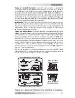
Connect a wire (same rating as the DC wires) to one end of the fuse
block and the other end of this wire to the positive terminal of the
fi
rst battery string (see Figure 2-8). This is essential to ensure even
charging and discharging across the entire battery bank.
Ensure the DC wire connections (to batteries, inverter, and fuse lugs/
DC circuit breaker) are
fl
ush on the surface of the DC terminals, and
the hardware (lock washer and nut) used to hold these connections
are stacked correctly (see Figures 2-6 and 2-7).
Verify DC connections torqued from 10 to 12 ft-lbs (13.6 to 16.3 N m).
Once the DC connections are completely wired and tested, coat the
terminals with an approved anti-oxidizing spray.
Press the red and black terminal covers onto the inverter’s DC
connectors to secure them in place.
If batteries are in an enclosure, perform a
fi
nal check of the hold down
brackets and all connections. Close and secure the battery enclosure.
Figure 2-8, Battery String Connections
String 2
String 1
12 volt battery bank
6 volts
6 volts
6 volts
6 volts
(First)
(Last)
BTS connection
Note:
Above applies only in systems
with more than one battery string.

