© 2017 Sensata Technologies
24
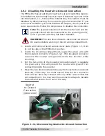
Strain
reliefs
Hot
Out
(red)
Neutral Out
(white w/
black
stripe)
Neutral
In
(white)
AC
OUTPUT
AC
INPUT
AC
Ground
In/Out
(green)
Neutral to
Ground
Connection
Hot
In
(black)
Figure 2-9, AC Wiring Connections (MMS1012 model)
2.4.6 AC Output Wiring
CAUTION:
The inverter’s AC output must never be
connected to an AC power source. This will cause severe
damage to the inverter and is not covered under warranty.
Info:
When using the MMS Series inverter in an RV
application—under certain conditions and provided that
the wire is properly sized for the protecting breaker—
RVIA wiring standards will permit the breaker in the main
distribution panel and/or the supplemental breakers on the
inverter to provide adequate protection for the AC output
wiring. For more information on these requirements, refer
to the RVIA (www.rvia.org).
To hardwire the AC output of the MMS Series inverter:
1. Remove the 1/2” knockout on the AC Output Connection
(Figure 1-3, Item 9)—use a utility knife to cut thru the round slot.
2. Discard this knockout and install a 1/2” strain relief in the AC
Output opening. You may need to
fi
le the opening edge for
proper
fi
t.
3. Run a 2-conductor plus ground cable through the strain relief in
the AC OUT opening. Refer to Table 2-2 for the minimum wire size
and the overcurrent protection required for the AC output wiring.
4. Remove about two inches (5.1 cm) of the insulating jacket from
the AC cable, and then separate the three wires and strip about
3/4” (1.9 cm) of insulation from each wire.
Installation

