MAINTENANCE
112
b. Remove
J15
c. Remove the buss-bar bolt to the
lower right DC heat-sink buss.
d. Remove 4 #10 screws from the
outside of the chassis. Two on the
bottom near the fan. Two on the
lower right side.
e. Pull out and up on the buss-bar
connection for fuse F4. The entire
assembly should come out, including
the current transducer.
2. Re-install:
a. Assemble the buss bars through the
replacement transducer. Apply
Joint-Al-Z to the buss bar interfaces.
Screw in the bolt for the buss bar to
F4 only finger tight.
b. Slip the loose parts into the chassis
from the top side, the reverse of 1)e)
above.
c. Align the transducer module
mounting holes with those in the
chassis. Start all 4 chassis
mounting screws and then tighten
them to 10 inch-pounds.
d. Start the lower buss-bar bolt
e. Remove J31 from the Signal
Interface PCB. Lift this PCB to
temporarily remove and bend
connecting wires out of the way for
access to the upper buss bolt by the
current transducer.
f. Place the upper buss bar over the
fuse mounting stud.
g. Now tighten both buss bar bolts to
40 inch pounds.
h. Replace the Signal Interface PCB.
Plug in J31 and J15.
i. Replace fuse F4. Be sure to use
the same washer / spacer
arrangement to achieve flat
mounting of the fuse tangs at both
ends. Re-tighten fuse mounting to
70 inch-pounds
Summary of Contents for DSD 412
Page 1: ...DSD 412 DC Elevator Drive Technical Manual CS00407 rev 06...
Page 6: ...6...
Page 102: ...MAINTENANCE 102 Figure 24 Connector and E prom Locations...
Page 103: ...MAINTENANCE 103 Figure 25 Test Point Locations...
Page 115: ...OUTLINE DRAWING 100A 115 Figure 26 Drive Chassis Outline DSD 412 100 Amp...
Page 116: ...OUTLINE DRAWING 190A 116 Figure 27 Drive Chassis Outline DSD 412 195 Amp...
Page 117: ...OUTLINE DRAWING 300A 117 Figure 28 Drive Chasis Outline DSD 412 300 Amp...
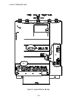
Page 118: ...LAYOUT DRAWING 100A 118 Figure 29 Layout DSD 412 100 Amp A3 A1 A2 A2 L1 NEG GND L2 L3 POS...
Page 119: ...LAYOUT DRAWING 195A 119 Figure 30 Layout DSD 412 195 Amp A3 A1 A2 A2...
Page 120: ...LAYOUT DRAWING 300A 120 Figure 31 Layout DSD 412 300 Amp A3 A1 A2 A2...
Page 121: ......


