STANDARD CONTROL/DISPLAY OPERATION
41
code is currently being viewed. If the error in
this slot is a Numeric Underflow fault 102 for
example, the SCDU will display:
1 0 2
Green LED Lit
Other errors currently in the Error List can be
viewed by pressing the ENTER
key to display
the Error Code again, then use either the
▲
or
▼
key to move to the next slot in the
list. The procedure outlined above should be
repeated as necessary to view the Error Code
number for other errors in the Error List.
Non-Volatile Ram Access
Every parameter that the drive uses has three
separate areas in memory associated with it.
There is a factory-set default value for each
parameter which is stored in the “read only”
EPROM chips. There is an area in the active
RAM which the drive uses while it is running.
There is also an area in NVRAM reserved for
each parameter. The values in the NVRAM
area are copied to the active RAM every time
the drive is powered up or the reset button is
pressed. This split level approach makes it
possible to return to the last set of ‘stable’
parameters in NVRAM if some errors are
made during fine-tuning of the active drive
parameters. The purpose of this function is to
perform transfers between the NVRAM
parameter list and the active parameter list.
Function 994 is used to perform the transfer of
data between the NVRAM and active
parameter lists. The process for copying data
to or from the NVRAM parameter list is as
follows:
1) Use the
▲
and
▼
keys to select
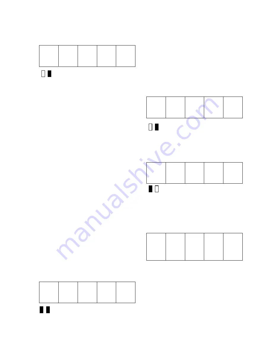
function 994 from the function level. The two
colored LEDs remain off during this step.
9 9 4
Both LEDs Off
2) Press the DATA/FCTN key to enter the
"Data" level for function 994. The green LED
is now lit to indicate that this function is
currently being accessed. It is possible to
SAVE the current active parameters in RAM
to the NVRAM parameter list, or to RESTORE
the current parameters from the NVRAM
parameter list to ACTIVE RAM.
Note that a
RESTORE is the same operation that occurs
inherently every time the drive is powered up.
Upon entering the data level for this function,
the SCDU displays:
r E S t
Green LED Lit
The
▲
and
▼
keys can be used to
toggle between the above display, which
indicates a pending RESTORE operation, and
the following display, which indicates a
pending SAVE:
S A V E
Red LED Lit
Note that as soon as either the
▲
or
▼
key is pressed, the red LED will light.
3) Press the ENTER key to actually perform
the transfer of data. If ENTER is pressed
while 'SAVE' is displayed, the SCDU display
may change to:
P r o t
This display means that the NV RAM
PROTECTION switch is in the incorrect
position preventing writes to the NVRAM.
Move the switch to the "OFF" position, press
the DATA/FCTN key, and start over from step
2.
Summary of Contents for DSD 412
Page 1: ...DSD 412 DC Elevator Drive Technical Manual CS00407 rev 06...
Page 6: ...6...
Page 102: ...MAINTENANCE 102 Figure 24 Connector and E prom Locations...
Page 103: ...MAINTENANCE 103 Figure 25 Test Point Locations...
Page 115: ...OUTLINE DRAWING 100A 115 Figure 26 Drive Chassis Outline DSD 412 100 Amp...
Page 116: ...OUTLINE DRAWING 190A 116 Figure 27 Drive Chassis Outline DSD 412 195 Amp...
Page 117: ...OUTLINE DRAWING 300A 117 Figure 28 Drive Chasis Outline DSD 412 300 Amp...
Page 118: ...LAYOUT DRAWING 100A 118 Figure 29 Layout DSD 412 100 Amp A3 A1 A2 A2 L1 NEG GND L2 L3 POS...
Page 119: ...LAYOUT DRAWING 195A 119 Figure 30 Layout DSD 412 195 Amp A3 A1 A2 A2...
Page 120: ...LAYOUT DRAWING 300A 120 Figure 31 Layout DSD 412 300 Amp A3 A1 A2 A2...
Page 121: ......


