INTRODUCTION
20
Power Conversion Unit
Description
The Power Conversion Unit circuitry has
three major functions;
1. It converts three phase AC input power
to variable DC voltage for application to
a motor armature.
2. It converts motor generated DC power
to three-phase power to feed back to the
line.
3. It converts single phase AC input power
to a variable DC voltage for application
to a motor field.
Two sources of power are required. A three-
phase power isolation transformer adjusts
the utility mains voltage to that required to
operate DSD 412 efficiently with the needs
of the DC hoist motor. 115VAC control
power from a separate source is used to
power the low voltage power supply, cooling
fans, relay and contactor logic.
Three phase input power is applied through
the AC line fuses to twin 6-SCR power
bridges for forward and reverse control. The
PCU microprocessor controls armature
current based on a reference received from
the Drive Control Unit microprocessor.
Output from the PCU microprocessor is sent
to the Armature Interface PCB, which
produces the gating signals for power SCRs.
The SCR bridge output is an adjustable DC
voltage, which is applied to the motor
armature circuit. Power circuit AC and DC
measurement signals are routed to voltage
dividers on the Armature Interface PCB, and
scaled values are sent to the PCU
microprocessor. Armature current is also
measured and the feedback signal is routed
through the Armature Interface PCB to the
PCU microprocessor. An over current trip
function monitors this signal to initiate an
instantaneous static trip (IST) in the event of
excessive output current.
Single-phase power is also applied through
the AC line fuses to the Field Rectifier
Module. SCR gating signals from the PCU
microprocessor control the field rectifier
SCRs. A separate current measuring device
is used to monitor the DC current flowing to
the motor field. Additional connections allow
for a separate step-up or step-down
transformer to be used to power the motor
field rectifier from voltage mains different
from that for the motor armature.
If optional dynamic braking resistors (DBR)
are present they are applied across the
motor armature to dissipate rotational
energy whenever the loop contactor is
dropped out. This helps to bring the motor
to a stop even when utility power is lost.
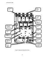
The largest component of the PCU is the
SCR bridge (Heat Sink Assembly). The heat
sink is an extruded aluminum structure that
dissipates the heat generated by the SCRs
mounted on the front surface (or between
heat sink sections, in large size power
cubes). The SCRs control the current to the
motor armature and in turn are controlled by
the Armature Interface PCB mounted in front
of the SCRs. Three input power line fuses
are provided. A DC Bus fuse protects the
motor armature circuit. A thermistor (and
thermostat on some ratings) senses heat
sink temperature and gives an over-
temperature warning if an over-temperature
occurs.
Access to the SCR Bridge is obtained by
opening the hinged door containing the
Drive Control PCB A1.
WARNING
Opening the hinged door with power applied
to the drive exposes dangerous voltage
levels. The hinged door should only be
opened by a qualified service technician,
and only when the power to the drive is
turned off.
Hardware Descriptions
DSD 412 Power Supply PCB (A4)
Pr5V, +15V, -15V, and +24V to the
control circuits and has fold-back current
limit protection. It also provides 115VAC
connections for the main contactor, motor
thermostat and fans.
Armature Interface PCB (A2)
Provides the interface circuitry between the
digital firing pulses generated by the Drive
Control PCB and the high current SCR
gating pulses controlling the armature
current. It also provides feedback signals
Summary of Contents for DSD 412
Page 1: ...DSD 412 DC Elevator Drive Technical Manual CS00407 rev 06...
Page 6: ...6...
Page 102: ...MAINTENANCE 102 Figure 24 Connector and E prom Locations...
Page 103: ...MAINTENANCE 103 Figure 25 Test Point Locations...
Page 115: ...OUTLINE DRAWING 100A 115 Figure 26 Drive Chassis Outline DSD 412 100 Amp...
Page 116: ...OUTLINE DRAWING 190A 116 Figure 27 Drive Chassis Outline DSD 412 195 Amp...
Page 117: ...OUTLINE DRAWING 300A 117 Figure 28 Drive Chasis Outline DSD 412 300 Amp...
Page 118: ...LAYOUT DRAWING 100A 118 Figure 29 Layout DSD 412 100 Amp A3 A1 A2 A2 L1 NEG GND L2 L3 POS...
Page 119: ...LAYOUT DRAWING 195A 119 Figure 30 Layout DSD 412 195 Amp A3 A1 A2 A2...
Page 120: ...LAYOUT DRAWING 300A 120 Figure 31 Layout DSD 412 300 Amp A3 A1 A2 A2...
Page 121: ......


